


| FAQ |
| Members List |
| Social Groups |
| Calendar |
| Search |
| Today's Posts |
|
#1
 12-18-2017, 12:58 PM
|
||||
|
||||
|
I'm working on a 70 GTO that we could not get the blower to work on. Several auto techs have fooled with it. Finally the last guy determined that if we unplugged this switch the blower would work on all four speeds. I'm assuming it means that part is bad? They are very hard to find and are not reproduced, so I'm gonna try to find a used one. Is this part necessary for the system to work, any ideas?
|
|
#2
01-09-2018, 02:32 PM
|
||||
|
||||
|
Where is the ambient air switch? Never heard of one but that doesn't mean they don't exist.
__________________
1967 Firechicken, 499", Edl heads, 262/266@0.050" duration and 0.627"/0.643 lift SR cam, 3.90 gear, 28" tire, 3550#. 10.01@134.3 mph with a 1.45 60'. Still WAY under the rollbar rule. |
|
#3
01-09-2018, 02:51 PM
|
||||
|
||||
|
It's a sensor mounted on top of the fan housing that senses the outside temperature in order to affect AC operation. Looks kind of like a transistor.
Been a while since I've looked at that circuit. I'm not sure what it would have to do with blower...although I do seem to recall a coil or coils of wire on the bottom side of it that controls the speed settings on the blower? Kind of foggy but I recall something along those lines.
__________________
Greg Reid Palmetto, Georgia Last edited by Greg Reid; 01-09-2018 at 02:58 PM. |
|
#4
01-09-2018, 03:28 PM
|
||||
|
||||
|
The thing with the coils is the blower fan speed resistance coils, they hang into the path of the blowing air to keep them cool. Far as I know they have nothing to do with sensing ambient air temp.
|
|
#5
01-09-2018, 03:56 PM
|
||||
|
||||
|
Yeah, I'm combining two devices in my mind....resistance coils and ambient sensor.
Sensor  Fan coils 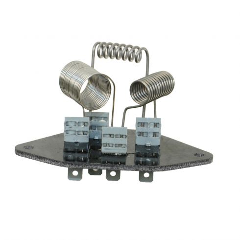
__________________
Greg Reid Palmetto, Georgia |
|
#6
01-09-2018, 05:05 PM
|
||||
|
||||
|
The temp sensor is usually mounted on top of the cowl if I remember right. Next to the blower air inlet at the base of the windshield on the passenger side. There so it doesn't catch underhood heat I think.
I'll see if I can find a picture. |
|
#7
01-09-2018, 05:12 PM
|
||||
|
||||
|
Here is a pic of one.
|
|
#8
01-09-2018, 05:13 PM
|
||||
|
||||
|
I think the resistance coils are mounted on the blower motor case outlet.
|
|
#9
01-09-2018, 06:16 PM
|
||||
|
||||
|
Thats the part in question. I ordered one from a guy on the forums but it hasnt come yet.
Sent from my iPhone using Tapatalk |
|
#10
01-09-2018, 06:20 PM
|
||||
|
||||
|
Sent from my iPhone using Tapatalk |
|
#11
01-09-2018, 07:39 PM
|
||||
|
||||
|
The ambient air switch is designed to keep the compressor from coming on if the temperature is below freezing to keep ice off of the AC system (as far as I can tell). It shouldn't impact the blower speed, but if it's bad and dragging the voltage of the entire AC system down back to the head unit in the dash, it might keep the blower motor from having enough voltage to spin.
|
|
#12
01-10-2018, 01:09 AM
|
||||
|
||||
|
Here is a scan from my rare and valuable original factory 68 diagnostics manual .. at least I think it's rare and valuable. It's got more info on AC that you could possible need to know.
Anyway, as Ben says, it is a normally closed switch that opens below 32 degrees to prevent the compressor clutch from activating. It is "in-line" in the power wire to the compressor clutch. Looking at the schematic I don't see how it could effect blower speed. It taps into power at the blower motor speed switch, but it's only a common tap off the blower switch main power lug that comes from the master relay. Only way I can see removing it would change anything is if it was grounding the power out through a faulty AC clutch, or a grounded AC clutch wire ... but then it would blow the fuse for the whole system I think. If you can't find one ... you COULD just jump the connector since the switch is normally closed ... you'd just have to remember not to turn on the AC when it's below freezing. |
|
#13
01-10-2018, 01:18 AM
|
||||
|
||||
|
Here is an overall wiring and connection diagram ... this is for a Firebird ..but I'm sure the system is the same for a Tempest/GTO
You can magnify it and it reads better ... or I can email a larger file. I'm seeing that part for sale as reconditioned for about $60 ... and some NOS examples for over $100. I would strongly advise testing it first, since according to the schematic that should not be the part causing the problem. Last edited by dataway; 01-10-2018 at 01:23 AM. |
|
#14
01-10-2018, 02:00 AM
|
||||
|
||||
|
First test I would make is unplug the AC clutch wire, reinstall the old ambient temp sensor, move the lever to HEAT, and turn the blower on high.
This would isolate the AC clutch as a problem, and bypass the resistor block. When the blower is on high, power runs direct to the blower and does not go through the resistor block. If the blower runs with the AC clutch wire disconnected then the AC clutch is probably the problem. Or could be some hinky problem in the Control Head (Dash board controls) they are pretty complex and get a lot of wear. |
|
#15
01-10-2018, 09:11 AM
|
||||
|
||||
|
Looking at the top schematic, it looks to me like removing the ambient switch from the circuit removes the ground path from the master relay fixed contact. I don't see how it could run without that. I may be missing something.
One thing is, what is the 'LO' setting's path to the blower motor?
__________________
Greg Reid Palmetto, Georgia |
|
#16
01-10-2018, 01:24 PM
|
||||
|
||||
|
Greg, note the brown wire from the Master Relay directly to the Resistor Block. Anytime the Master Relay is energized the blower runs on LOW unless the speed switch is set to another speed. So technically there is no actual discreet "LOW" setting, it is the base line speed for the blower whenever either heat or cool is turned ON.
The fixed contact on the Master Relay is not grounded, power enters through the 30 amp fuse and is sent through the two brown wires when closed. The relay coil is grounded locally at the relay and energized by gray wire from the dashboard controls. The Ambient Switch will interrupt power to the clutch, which is grounded. But the system isn't grounded THROUGH the clutch ... since that would activate it. Trying to understand that other Firebird operational schematic is a nightmare, I'd have to print out five copies of it and trace wires with a high-liter pen to make sense of it 
|
|
#17
01-10-2018, 01:52 PM
|
||||
|
||||
|
Oh yeah. I see the brown wire now for 'LOW' and that the blower motor supplies it's ground regardless of ambient switch closure. Didn't study it long enough.
__________________
Greg Reid Palmetto, Georgia |
|
#18
01-10-2018, 06:25 PM
|
||||
|
||||
|
OK, I hooked up ambient switch and unhooked wire to compressor...blower ran for a second and then instantly blew the fuse in fuse box.
Hooked compressor back up, unplugged ambient switch and blower runs in all four speeds. Sent from my iPhone using Tapatalk |
|
#19
01-10-2018, 07:12 PM
|
||||
|
||||
|
According to that schematic posted above, blower feed comes from 30 Amp fuse by alternator. So does feed to Ambient Switch and Clutch coil.
Ambient Switch and Clutch Coil are only fed when you are in the AC mode. Frd by Cluch Switch in control head. Blowing fuse in fuse box would have to be on brown lead to Master Switch in control head or Master Relay itself. Last edited by Old Goat 67; 01-10-2018 at 07:21 PM. |
|
#20
01-11-2018, 12:17 AM
|
||||
|
||||
|
Look for a short in the wire to the AC Clutch.
When you remove the ambient switch it is isolating the AC clutch wire, so it doesn't blow a fuse. If the wire to AC Clutch wire is grounded/shorted somewhere, when you install the ambient switch it is completing the path to ground and blowing the fuse. In post 12 I mentioned the possibility of blowing a fuse with a faulty AC clutch wire. Since the ambient switch has two black wires, you'll have to find which one leads to the AC Clutch. That's the one you want to check for a short. If you are handy you can test the wire to the AC clutch for a short by unplugging it from the AC, and unplugging it from the ambient switch and use a volt/ohm meter to see if it is grounded. Blowing a fuse when you plug in the ambient switch is telling you there is a short DOWN STREAM of the switch since the switch is normally in the ON position. I am assuming the AC is turned on during your tests ... otherwise there should be no current flowing to the AC Clutch to short out. If the AC is turned off, the ambient switch is installed, and it still blows a fuse ... then there is something else amiss, wires hooked up wrong somewhere, some fault in the control head. With the AC off there should be NO power going to the ambient switch. Just keep in mind the ambient switch is NOT your problem, it is just a simple thermostatic switch, what it IS doing is providing a path to ground for some other problem that is blowing the fuse. Make sure the ambient switch itself does not have any wires exposed, touching any metal etc. Hopefully that switch handled the 30 amps to blow the fuse without frying. PS. One caveat ... the older ambient switches had a metal base ... I supposed it's conceivable it could have a short to ground inside the switch, which would blow the fuse. The later model switches (still compatible) had a fiber base that would prevent a short in the event the switch had an internal fault. On a switch with a metal base you could test this by testing continuity between either connection on the switch, to the metal mounting plate. There should be no continuity between the metal mounting base and the two wire connections. Yes, diagnosing this stuff remotely is very tough. If I was there with a VOM I could probably find the fault in ten minutes. We haven't even gotten to the fact the AC Clutch switch in the Control Head could be stuck in the ON position
Last edited by dataway; 01-11-2018 at 12:37 AM. |
| Reply |
|
|
The PY Online Forums is the largest online gathering of Pontiac enthusiasts anywhere in the world. Founded in 1991, it was also the first online forum for people to gather and talk about their Pontiacs. Since then, it has become the mecca of Pontiac technical data and knowledge that no other place can surpass.


 Linear Mode

