


| FAQ |
| Members List |
| Social Groups |
| Calendar |
| Search |
| Today's Posts |
|
#1
 07-28-2010, 12:21 AM
|
||||
|
||||
|
OK dont hate me. I spent 2 hours last night reading all of the posts here and elsewhere about the FAN not working on HI. Still need help. Mainly as there were not good photos that can make it clear to me. I reviewed my manual and the wiring diagrams but no diagrams for any year show a red wire.
75 Formula with A/C I am putting it all back together and I cant get the fan to work on HI and it doesnt blow lightly on "Lo" (I dont recall if it did before but I heard that it is supposed to. It Does work on 2 - 3 I took everything apart and redid everything in the engine bay in my engine / tranny rebuild. Wiring was not hacked up. I labeled everything and even have old BEFORE pics.
My Blower Fan worked on all speeds before removal. I have read about the RED WIRE that is supposed to be connected to the Relay. I cannot find that wire or where it is supposed to connect to the relay. I have attached pics my my A/C harness and all connectors. I have 1 red wire on the terminal on the Alternator that goes to the Battery. In all of my before photos I cannot see a second red wire that was attached to the alternator. It occured to me that it COULD have been attached at the battery terminal cable. But I still cannot see where it connects to the A/C Relay. I have 2 fan switches and I tried both. same thing. I dont quite know where to check for voltages since I cant see where I'm supposed to get Hi Speed power.. I Need help on how to wire HI speed. Do I need a NON A/C Relay now? I've read that in some posts. The only "Hack" in the harness is where I installed a circuit breaker at the suggestion of my A/C Mechanic back when I had a bad clutch replaced on my A6 compressor. That's the circuit breaker on the Yellow and Orange wires.    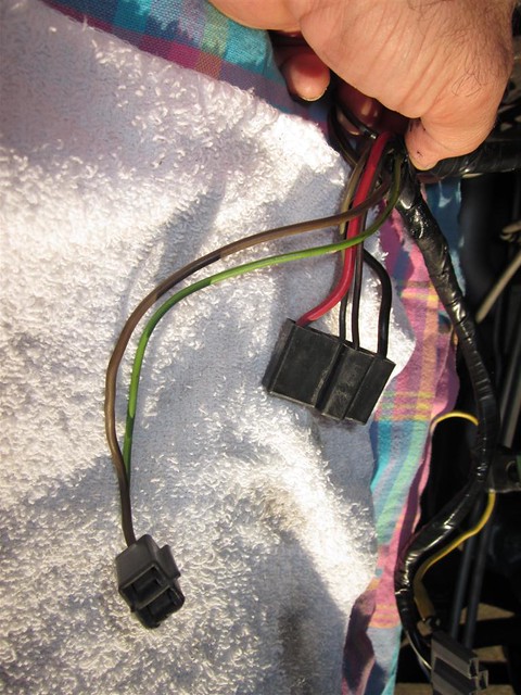  
__________________
-- James Work '67 GTO Convertible "Koerner Built 413 500 hp with a Victor!.. I'll run a stock intake." '75 Formula 400 - Daily Driver - Running with my Home Built 455 and TH400 Details here: http://forums.maxperformanceinc.com/...d.php?t=588372 |
|
#2
07-28-2010, 07:11 AM
|
|||
|
|||
|
Not having looked for a wiring diagram, doesn't that large brown/yellow wire go to a fuse at the output terminal of the alternator?
__________________
Lee Peterson ------------- "I didn't expect a kind of Spanish Inquisition...!" '69 Cameo White RA III Judge, 4 speed, owned since 1977 -- my first car. |
|
#3
07-28-2010, 07:19 AM
|
||||
|
||||
|
Is there 12v at the big red wire to the relay and if there is see if it will power up a headlight or blower motor. May have high resistance in the circuit.

__________________
1971 Pontiac GT-37 Car is a junk yard dog and maybe one day will be restored. 
|
|
#4
07-28-2010, 07:33 AM
|
||||
|
||||
|
Do you have a schematic you can post?
|
|
#5
07-28-2010, 04:08 PM
|
||||
|
||||
|
Charles-
I dont have one here at work. I did search the web for about an hour and didnt find one. Ill scan and post what I have in my manual when I get home. Thanks a lot,
__________________
-- James Work '67 GTO Convertible "Koerner Built 413 500 hp with a Victor!.. I'll run a stock intake." '75 Formula 400 - Daily Driver - Running with my Home Built 455 and TH400 Details here: http://forums.maxperformanceinc.com/...d.php?t=588372 |
|
#6
07-28-2010, 04:22 PM
|
||||
|
||||
|
|
|
#7
07-28-2010, 10:56 PM
|
||||
|
||||
|
Well I appreciate the help. especially from Old Goat.
Thanks for the help. I ended up drawing what wiring I have since I went out and traced everything down.. I did discover that I DO have a Red wire going to the Alternator. I didn't think it was the same wire going into the Plug on the Alternator but it was. That's because the wire has a "fusible Link" (I guess) in that it steps down from a larger gauge to a smaller gauge under the loom/tape. Then it ends in the 2 terminal Plug on the alternator along with a green wire. I found that if I jump the wires between the RED and the Black/Orange on the Relay connector I can get HI to work. Not sure what is wrong but it appears that the Relay is not making that connection on HI? The voltages were all measured at the Relay Connector with it plugged in to the Relay. Thanks
__________________
-- James Work '67 GTO Convertible "Koerner Built 413 500 hp with a Victor!.. I'll run a stock intake." '75 Formula 400 - Daily Driver - Running with my Home Built 455 and TH400 Details here: http://forums.maxperformanceinc.com/...d.php?t=588372 |
|
#8
07-29-2010, 12:20 AM
|
|||
|
|||
|
Are you saying that the red wire from the relay goes to the two-wire plug on the alternator? It shouldn't. The power to the high-blower relay on most GM cars of that era came from a fuse connected to the output stud of the alternator. I'm *fairly* sure that should be the brown/orange wire. We really need a wiring diagram -- I couldn't find one online without paying.
Edit: OK, now I see where the brown/orange wire goes. The red should go to the output stud. The relay makes contact between the brown/orange and red to give hi blower. If the grey wire is power to the relay coil the brown wire should ground to turn the relay on. I think something's funny with your wiring to the compressor -- not sure why there would be a circuit breaker there.
__________________
Lee Peterson ------------- "I didn't expect a kind of Spanish Inquisition...!" '69 Cameo White RA III Judge, 4 speed, owned since 1977 -- my first car. Last edited by LPete; 07-29-2010 at 12:42 AM. |
|
#9
07-29-2010, 06:02 AM
|
||||
|
||||
|
That is not really a circuit breaker, but a "thermal limiter". It will be connected with the super heat switch, which will pop and turn off compressor to prevent damage to compressor.
|
|
#10
07-29-2010, 07:25 AM
|
|||
|
|||
|
Quote:
I also don't see the power wire to the A/C clutch circuit that should be coming from the dash control. Some cars had an ambient switch that kept the compressor from engaging in cold weather, but that's not in the drawing (and I'm thinking they didn't use it in '75). Anyone have a wiring diagram?
__________________
Lee Peterson ------------- "I didn't expect a kind of Spanish Inquisition...!" '69 Cameo White RA III Judge, 4 speed, owned since 1977 -- my first car. |
|
#11
07-29-2010, 08:22 AM
|
||||
|
||||
|
Quote:
Can you scan the manual drawings? After all the hacking, it would be best to see the original engineered drawings. Charles |
|
#12
07-29-2010, 05:17 PM
|
||||
|
||||
|
The item labled Circuit Breaker is actually the Thermal Limiter, he is correct my lack of knowledge.. I have the compressor wires over on the other side of the motor for now so as not to confuse me. I didnt post a pic of that. I will.
The GREEN Circuit Breaker in the photos was something I added. So That IS a hack. But it's the only HACK that I can see. Everything functioned in that manner previously. Yes the RED wire from the Relay goes along the back of the motor and in the loom to the Alternator. Just before the Alternator it has a fusible link kind of connection and steps down to a smaller red gauge then to the plug. I did replace the PLUG on my Alternator as it was rather smashed up but the two wires in it were there already. A red and a green. Since this is the only thing I changed, this is one thing I may have screwed up? But I looked at my Alternator photos I took before I started pulling my engine, and there is only 1 red wire on the stud of my Alternator and it goes to the Battery. The only wires from the relay or resistors that go to the compressor are on the top right of the drawing. There is a single BROWN wire that goes to the THERMAL Limiter connector. That 3 wire connector has that BROWN wire, a GREEN wire and a BLACK wire: - GREEN wire comes out of that and goes to the 2 terminal connector plug on the compressor. - The single BLACK wire comes out of that Thermal Limiter connector and goes to the Superheat Switch on the Back of the Compressor. The 2 connector plug that is hooked to the compressor power and that GREEN wire has only a second short BLACK Ground wire coming out of it that was grounded to the Compressor bracket. My A/C compressor worked when removed with this harness. Ill scan the diagram from the manual. I'll also diagram the Control head harness. Thanks Gentlemen!
__________________
-- James Work '67 GTO Convertible "Koerner Built 413 500 hp with a Victor!.. I'll run a stock intake." '75 Formula 400 - Daily Driver - Running with my Home Built 455 and TH400 Details here: http://forums.maxperformanceinc.com/...d.php?t=588372 |
|
#13
07-29-2010, 09:07 PM
|
||||
|
||||
|
just by looking at the drawing of wires, I would suspect the brown wire is power from the relay going to the compressor to engage it.
|
|
#14
07-29-2010, 09:12 PM
|
||||
|
||||
|
I think that's correct Pepi.
Here is my wiring diagram. It omits the AC section entirely... Im going back out there and ill look at the red wire situation again right now..
__________________
-- James Work '67 GTO Convertible "Koerner Built 413 500 hp with a Victor!.. I'll run a stock intake." '75 Formula 400 - Daily Driver - Running with my Home Built 455 and TH400 Details here: http://forums.maxperformanceinc.com/...d.php?t=588372 |
|
#15
07-29-2010, 09:32 PM
|
||||
|
||||
|
Where is the rest of this of the car? Can you scan that too.
Look in the A/C section for a diagram of it. Charles |
|
#16
07-29-2010, 09:41 PM
|
||||
|
||||
|
I was trying to look in my books too, and it is weird that that is all that is shown. No wiring for the compressor or blower motor relays. Only power going to the switch and through the resistors then to the motor itself.
|
|
#17
07-29-2010, 09:45 PM
|
||||
|
||||
|
See if this helps:
__________________
John Wallace - johnta1 Pontiac Power RULES !!! www.wallaceracing.com Winner of Top Class at Pontiac Nationals, 2004 Cordova Winner of Quick 16 At Ames 2004 Pontiac Tripower Nats KRE's MR-1 - 1st 5 second Pontiac block ever! "Every man has a right to his own opinion, but no man has a right to be wrong in his facts." "People demand freedom of speech to make up for the freedom of thought which they avoid." Socrates |
|
#18
07-29-2010, 10:03 PM
|
||||
|
||||
|
I am baffled by the circuit breaker in the second picture, obviously non factory, but why would someone put that in there? Is the circuit breaker any good?, If it were me, I would get rid of it and repair the wire to go back to original. I have found a more detailed wiring diagram, but it is for a 73. Different colored wires, but maybe same principle for how it should work.
|
|
#19
07-29-2010, 10:10 PM
|
|||
|
|||
|
Quote:
James, I'm not sure I understand your answer about the red wire from the relay to the alternator. If it goes in the two-wire plug as it's wired now, it's wrong. That terminal at the alternator is the sense wire. The hot wire to the high blower relay should absolutely go to the output terminal of the alternator. Does it? Edit: In fact, if you look closely at the diagram you posted, it shows the red "A/C lead" connected to the output terminal.
__________________
Lee Peterson ------------- "I didn't expect a kind of Spanish Inquisition...!" '69 Cameo White RA III Judge, 4 speed, owned since 1977 -- my first car. |
|
#20
07-29-2010, 10:19 PM
|
||||
|
||||
|
I know there should be a fuse, mine is right at the alternator, I just thought it looked as though an orange piece of wire was spliced in, then the new blade style fuse spliced in. I totally agree that it looks like a breaker was put in instead of the fuse, and the power should be from the batt post of alternator, and not the sensing wire.
I'll scan what I have, again it is for a 73, if it is wanted to be posted I'll post it. |
| Reply |
|
|
The PY Online Forums is the largest online gathering of Pontiac enthusiasts anywhere in the world. Founded in 1991, it was also the first online forum for people to gather and talk about their Pontiacs. Since then, it has become the mecca of Pontiac technical data and knowledge that no other place can surpass.


 Linear Mode

