


| FAQ |
| Members List |
| Social Groups |
| Calendar |
| Search |
| Today's Posts |
|
#1
 02-01-2010, 06:59 PM
|
||||
|
||||
|
This is a thread about how to rebuild a Pontiac V-8.
I decided to post this thread after looking all over the internet for information on rebuilding Pontiac motors. There is no one thread devoted to this one topic. While it's true that rebuilding any type of motor shares many common techniques, each brand has its own special ins and outs. It's time to have a thread dedicated to Pontiacs only. I'm not claiming to be a Pontiac expert, and there are many engine rebuilding topics that Im not going touch on in this thread. The hope is that those of you with more experience rebuilding Pontiac V-8's will add to this thread, fill in the areas I missed, and add your own tips and pointers. Let's get started. First of all, it's a good idea to begin with a plan for your motor. Do you want a drag car that barely runs on the streets, or torque monster that will rule the streets? Trailer queen, or daily driver? Restification or concours? Since the original 400 in my 1969 GTO was long gone, I decided to do what a guy probably would've done back in the 1970s if he grenaded the original motor -- find a 428, install a better cam, swap over the GTO intake and carb, and go with better heads. 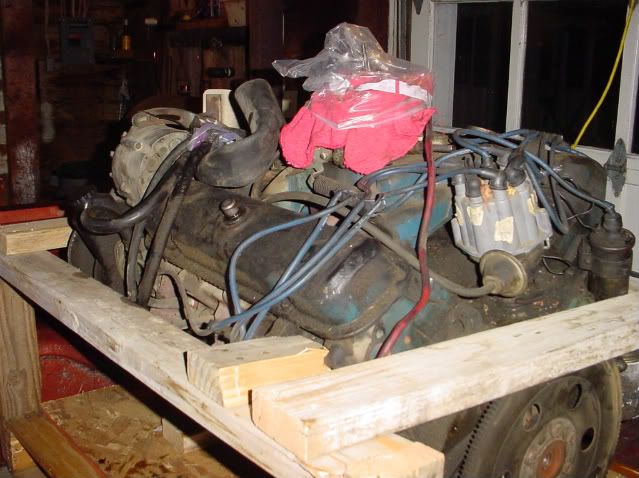 Our rebuild subject is a 1969 Pontiac 428. It is a so-called YH motor, which means it came from the factory with 46 heads, two bolt main caps, and a mild cam. In keeping with my theme, this motor was rebuilt using the 69 GTO intake and carb along with the hotter 068 cam. 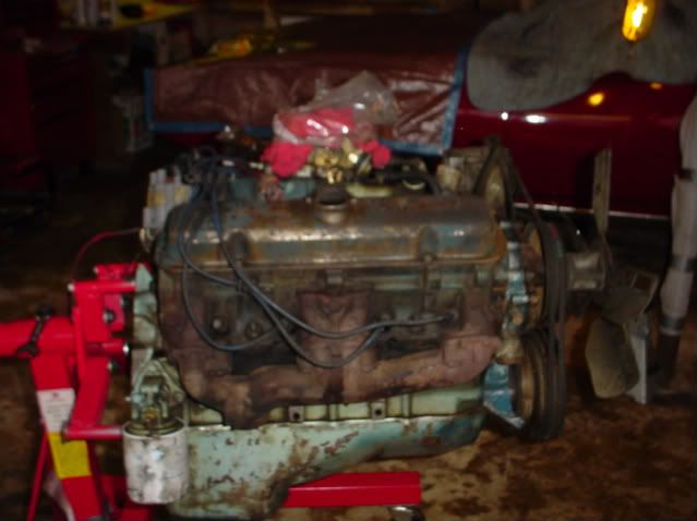 Doesn't look very clean on the stand, does it? I was hoping that the innards would look better than the exterior. 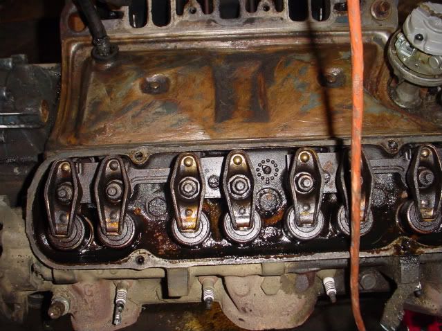 Next we pulled the intake and carb. Although the motor was not overly sludgy for its age, the oil was tired and smelled fried. This motor may have run recently, but could not have been running very well. 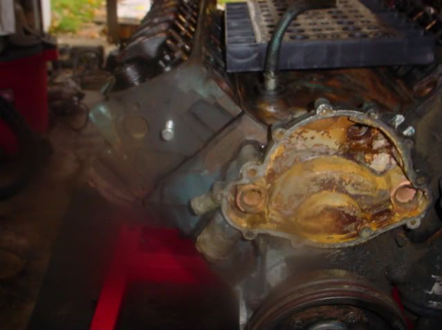 After the water pump came off the motor really started showing its age with some nasty pitting on the timing cover. 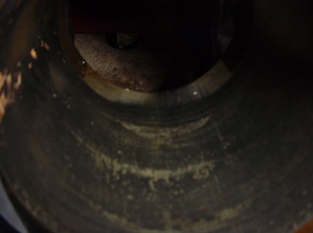 We pulled the heads off, looked at the cylinders, and there it was -- pitting, scratching, everything that says time for rebuild. 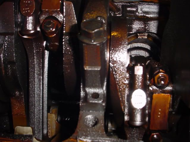 Now that we were committed to a total rebuild, it was time to get organized. The first thing we did was number the rods and the main caps so they could be reassembled in the right order. We didn't have number punches, so we used a series of dots to mark the rods and caps. Works fine as long as the marks are clear. We also made sure to bag and tag all of the many small parts that we removed from the engine. We made good use of the digital camera, taking as many pictures as possible so that we know where and how to reinstall the parts during the reassembly. 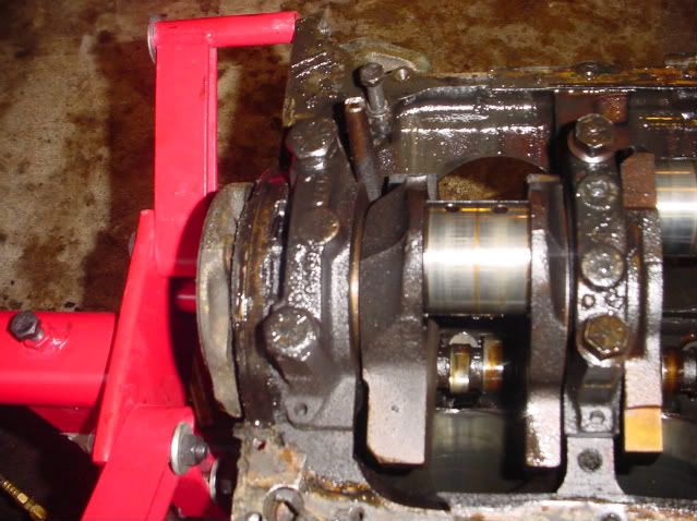 The rod journals were looking sort of rough. Although things looked bad, we couldn't catch a fingernail on the journal surface, which was a good sign. 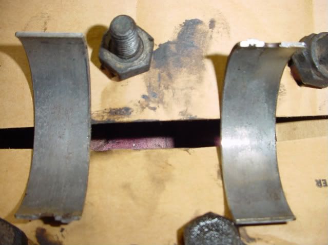 I forgot to mention that the oil pan had lots of nasty grit in it. By the looks of these rod bearings, that grit had found its way through the motor. 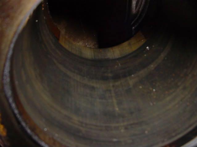 Here's a closer look at one of the cylinders. You can see the pitting and you can see where water accumulated down in the cylinder. No doubt this block needed to be bored. 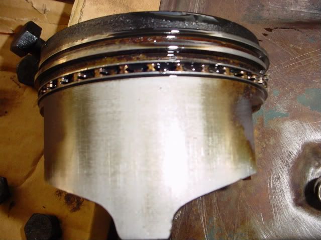 Not that any more reasons were needed, but here is a shot of one of the pistons showing scratching on the side. The other 7 were no better. Since the motor was going to be bored anyway, these pistons were junk. Ill be posting more soon.
__________________
"Pay no attention to the planet Mopar. It is a strange and confusing place." ~Chiphead |
|
#2
02-01-2010, 07:04 PM
|
||||
|
||||
|
We are now going to fast-forward to the to the assembly stage of the project.
Before we do, I'll describe the work that went on in the machine shop. First, I completed the disassembly of the motor and brought the pieces to the machine shop for cleaning. The block, crank, and rods were baked, blasted, and jet washed. After the block was completely clean it was maganfluxed to make sure there were no cracks. The block was then was align honed, decked, and bored 0.030 over. The machine shop installed the cam bearings, block plugs, and oil passage plugs. After the crank was cleaned, all it took was a polishing to make it serviceable. 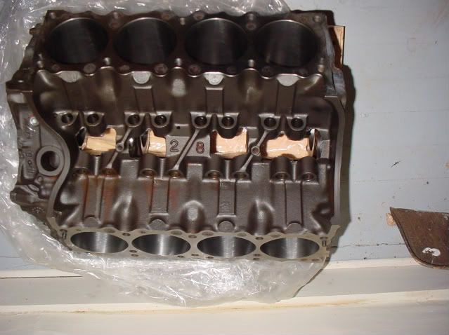 Here's how the block looked after it came out of the machine shop. Tip for Pontiac builders: pay close attention to the machine work where the rear main seal fits. If this is not accurate, your chances of a leaky rear main just increased. 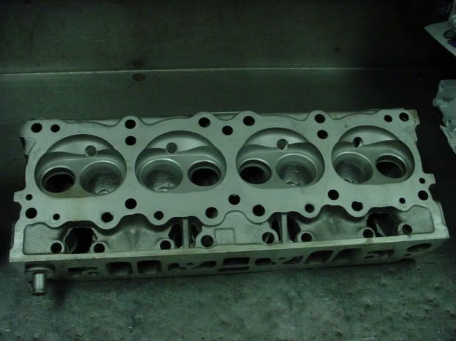 If you noticed I didnt talk much about the original heads, it's because I decided not to use them. The stock 46 heads made too much compression for the street motor that I wanted to build, so my machinist recommended a set of 6X (4) heads. The heads were decked, new valve guides were installed, and given a competition valve job. I let the machine shop assemble the heads. Since this was not a rush rebuild, the disassembly of the motor occur in the fall of 2008 and all the machine work occurred during following winter. During the spring and early summer of 2009, I cleaned all the other parts and bought whatever pieces that were needed, such as an oil pump. 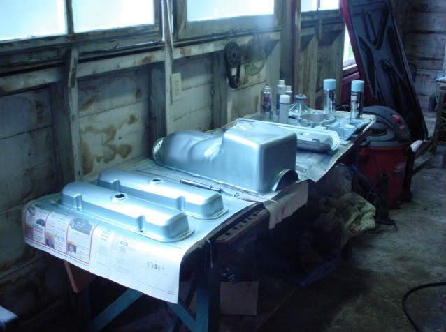 After all the parts are completely clean and dry, it is time to paint. In this photo you can see the valve covers, oil pan, valley pan, timing cover, and water pump. Many light coats will work better than one drippy one. 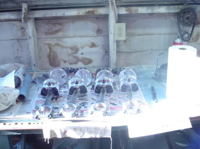 Here is a shot of the pistons hung on the rods. We let the machine shop do this work since they had the tools, and we didn't 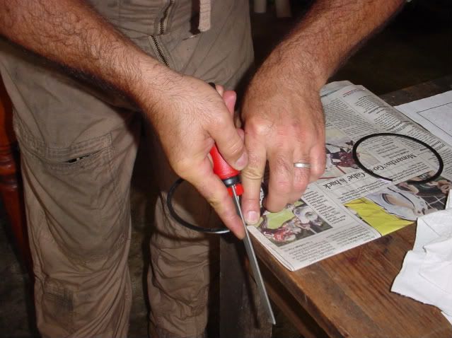 We begin the rebuilding process by file fitting the rings. If you've not built a motor before, it's a good idea to call on a friend who has. This is my friend Karl filing a ring (Karl is sort of like Waylon Jennings on the Dukes of Hazzard, you are only going to see is his hands not his face.) Karl is filing from the outside to the inside of the ring. This is so that there'll be no burr to catch on the cylinder. If you do create a burr, remove it with a fine stone. 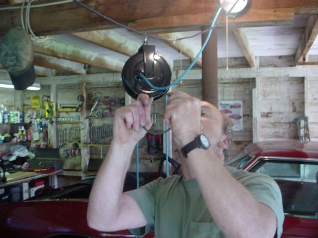 As you file the rings, you will need to stop frequently and check the ends of the ring for squareness. The best way to do this is to hold the ring up to the light, which is what I am doing in this picture. 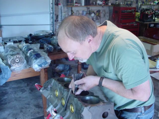 You'll also need to check your progress by installing the ring into a cylinder. Make sure the ring is square in the bore. Once installed, you can check the ring gap with a feeler gauge. Since I'm the one building the motor, we took the time to file fit all of the rings, cylinder by cylinder, to the exact specification called for by the ring manufacturer. 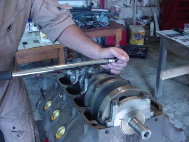 Now, we're going to do some more measuring. In this case were going to measure the clearance between the main bearings and the crank journals. This can be checked in several ways. If you happen to have a set of machinist gages, you could measure the ID of the bearing shell and that of the OD of the journal and calculate your clearance. The second, and more common way for amateur builders, is to use plasti-gage. To do this test, you need to install the bearing in the block. Lay the crank on the bearing halves. Next, you will need to place pieces of plasti-gage on each of the main bearing journals. With the plasti-gage in place, you then install the main bearing caps with bearing shells and torque them to specification (120 foot-pounds for the rear main, and 100 foot-pounds for the others) for a Pontiac 428. Make sure to immobilize the crank during this process, because if it moves it will spoil the reading. (You can see where we used a magic marker to make sure the crank didn't move relative to the main cap.) 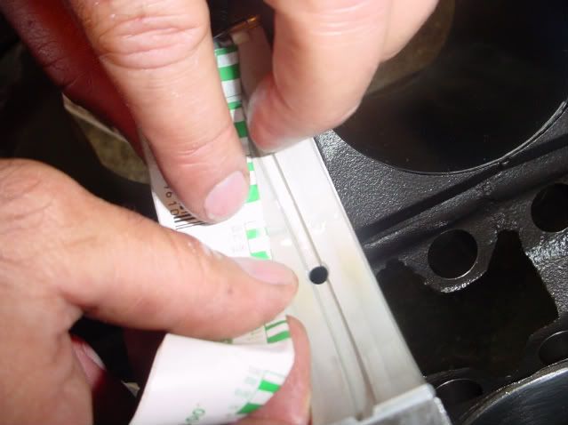 Once the mains are torqued to spec, loosen them up and remove the bearing shell. You will see that the plasti-gage has been squished. The tighter the clearance, the more squished the plasti-gage will be. The squished plasti-gage is then compared to the chart on the plasti-gage wrapper, which allows you to determine your clearance. Since this was my motor, we took the time to check all of the journals, not just one. This is another fast forward in the rebuilding procedure. I am skipping a very important part which is the temporary installation of the piston/rod assembliess on the crank for the purpose of checking rod bearing clearance. Plasti-gage can be used to check clearance for the rod bearings just as it's used for the main bearings. Some people will check only one bearing and call it good. We did them all just for my peace of mind.
__________________
"Pay no attention to the planet Mopar. It is a strange and confusing place." ~Chiphead |
|
#3
02-01-2010, 07:49 PM
|
|||
|
|||
|
Nicely done....
|
|
#4
02-01-2010, 08:05 PM
|
||||
|
||||
|
subbed for this.
|
|
#5
02-01-2010, 08:33 PM
|
||||
|
||||
|
How far 'down in the hole' are your pistons?
|
|
#6
02-01-2010, 11:37 PM
|
||||
|
||||
|
Quote:
__________________
"Pay no attention to the planet Mopar. It is a strange and confusing place." ~Chiphead |
|
#7
02-01-2010, 11:39 PM
|
||||
|
||||
|
This is another fast forward point in the documentation of the rebuild procedure. I am skipping a very important step, which is the temporary installation of the piston/rod assemblies for the purpose of checking rod bearing clearance. Plasti-gage can be used to check clearance for the rod bearings just as it's used for the main bearings. We checked for proper clearance for all 8 rods.
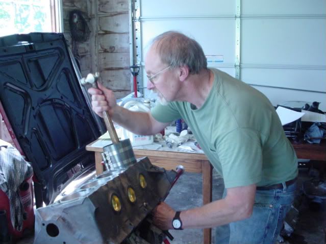 This is the process by which the piston/rod assemblies are installed into the block. You can see the ring compressor which allows the rings to be compressed enough to fit into the cylinder. To tap in the piston, you need to use something soft (such as the wooden hammer handle that I'm using) so you don't damage the top of the piston. It's equally important that you install some sort of protective rubber sleeve over the rod bolts so they don't scratch the crank during the installation process. 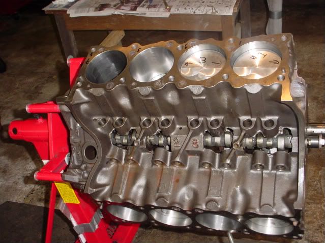 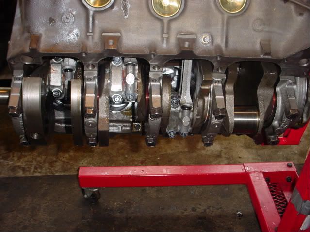 This is how the block will look as you add the piston/rod assemblies. As you rotate the crank after the installation of each piston, you should notice a steady increase in amount of effort it takes to turn the crank. Everything should turn smoothly, with no binding. If binding occurs, or it things just dont feel right, stop! Better to backtrack and correct any trouble spots now, because it wont get any easier later on. 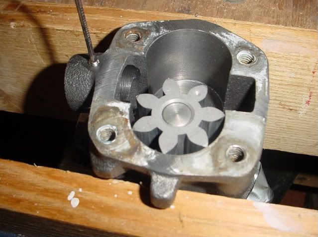 Even though it may be brand-new, don't forget to check the oil pump. I had read about cases where the oil pickup had separated. In order to prevent this from happening, I drilled and tapped for an 11/32 allan screw that provides an interference fit between the oil pump and the oil pickup. I also disassembled the pump to make sure there were no metal shavings or anything else that might interfere with the pump's performance. 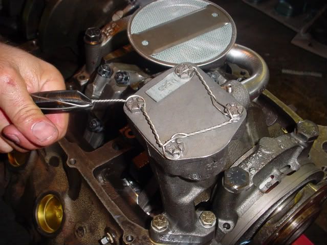 Here is the pump as installed in the block. The allen screw received a health dose of red loctite. As an additional margin of safety we wired the bolts to make sure nothing would come loose during operation. Some of you may feel this is overkill but, if you are building the motor, you get to satisfy your own comfort level. You will also need to adjust the oil pump pickup so it sits at the right height in the oil pan. A clearance of 1/4" to 3/8" from the bottom of the pan is about right, checked with pan gasket in place. 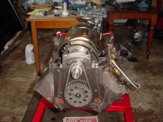 Here is the almost complete short block. All pistons are installed as are the windage tray, timing gears and timing chain. 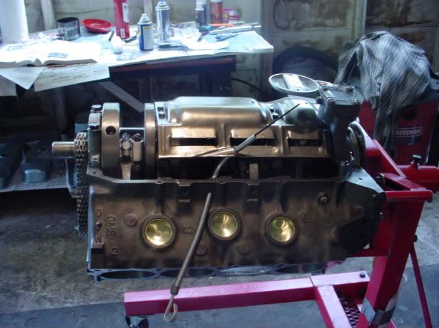 Another view of the short block. When rebuilding a Pontiac V-8, make sure you get the correct dipstick assembly as they do vary depending on year and the presence or absence of a windage tray. 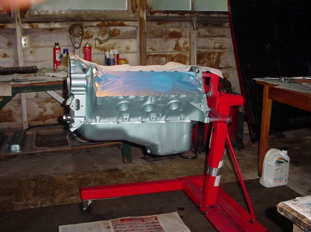 Here is a result of our first day of engine building -- a complete short block, less water pump. We started at seven in the morning and called it quits at five. After making sure the exterior of the block was clean and dry, I painted it later in the evening. So far, the time spent planning and organizing was time well spent. Almost every part we needed was ready to install and within easy reach. The same was true for tools and assembly supplies. The only things unaccounted for were the oil pump bolts, but after a quick trip to the hardware store we were back in business. In the next post well move on to the top half of the motor.
__________________
"Pay no attention to the planet Mopar. It is a strange and confusing place." ~Chiphead |
|
#8
02-01-2010, 11:46 PM
|
||||
|
||||
|
Quote:
|
|
#9
02-02-2010, 12:20 AM
|
||||
|
||||
|
I did not see any assembly lube on the camshaft lobes, or is the lube kinda grey in color?
__________________
" Is wearing a helmet illegal" Mike Kerr 1-29-09 |
|
#10
02-02-2010, 01:32 AM
|
||||
|
||||
|
Great thread! Keep it up!
__________________
Matt 70 GTO 400 4-speed "Turbos make no noise and leave the line like Baby Diarrhea!" - GTOGeorge |
|
#11
02-02-2010, 01:54 AM
|
|||
|
|||
|
Red Coupe,
Great post!! It will be very helpful to the members that have never built an engine. It's really NOT rocket science!! |
|
#12
02-02-2010, 05:42 AM
|
||||
|
||||
|
Great thread....I'll be doing the same thing in a few months (first time on a Pontiac).
The ring gap, piston to cyl wall clearance & plasi-gage measurements would be nice ? Cam intallation.. was it degreed in, or just lined up the dots ? Rear main seal install .. any trimming, make ? Looking forward to the rest, hope you do a detailed valve train geometry check for the beginners to see. I'll be back. 
__________________
'74 Formula car is gone and I will be posting under my old 2004 (newly discovered old account from a work computer) "PONTIAC-ONE" from now on. I totally forgot I had that. R.I.P. "1974formula" 
Last edited by 1974formula; 02-02-2010 at 05:44 AM. Reason: Sp |
|
#13
02-02-2010, 08:30 AM
|
||||
|
||||
|
Nice build.
No mention of decking/squaring up the block? We consider this a manditory step, and take the extra time to establish zero deck height by mocking up the engine and measuring the outer 4 corners before sending it out. Quench distance is very important on a Pontiac build, more-so than with some other makes. I used to have a YH 428 in my Ventura 20 something years ago. It had the pistons apprx .018 in the holes and .039" head gaskets. Even at 8.8 to 1 SCR and a tad more cam than you are using, it was prone to run too hot for my liking, and on occassion would ping on hot summer days. We started zero decking after that engine, and none of them even think about running hot/overheating/detonation, and manage lower octane at higher compression ratios. Another helpful tip is to clamp the file in a soft jawed vise to file the rings. Much easier to keep them straight and square working against a stationary file than filing them free-hand. I'm sure Karl is good at it, so it's just a minor point. Last item, keep the #46 heads around, they make great heads for 400 builds. We take them out to 2.11/1.77 for the valves, add the outer bolt holes for the exhaust manifolds/headers, screw in studs and you have an excellent set of heads. They end up being better than most big valve heads as you can get all the valves at the same height in the chambers working with the "virgin" material. Most sets I've had in here come in around 75-78cc, establishing an ideal CR on a 400 engine with flat top pistons and zero deck height......Cliff
__________________
If you can read this, thank a teacher. If you can read this in English, thank a Veteran! https://cliffshighperformance.com/ 73 Ventura, SOLD 455, 3740lbs, 11.30's at 120mph, 1977 Pontiac Q-jet, HO intake, HEI, 10" converter, 3.42 gears, DOT's, 7.20's at 96mph and still WAY under the roll bar rule. Best ET to date 7.18 at 97MPH (1/8th mile), |
|
#14
02-02-2010, 09:45 AM
|
|||
|
|||
|
All ears! Keep 'er coming..
__________________
1969 LeMans vert, 400 1971 Corvette 1964 Cadillac Deville so far.... http://s233.photobucket.com/albums/e...1969%20LeMans/ |
|
#15
02-02-2010, 10:20 AM
|
|||
|
|||
|
good info for us rookie engine assemblers. How much did all the machine work cost?
|
|
#16
02-02-2010, 06:01 PM
|
||||
|
||||
|
Nice thread.
__________________
Nothing in the world can take the place of persistence. Talent will not; nothing is more common than unsuccessful men with talent. Genius will not; unrewarded genius is almost a proverb. Education will not; the world is full of educated derelicts. Persistence and determination alone are omnipotent. The slogan Press On! has solved and always will solve the problems of the human race. ― Calvin Coolidge |
|
#17
02-02-2010, 07:30 PM
|
||||
|
||||
|
4dblnkldude - Yep, the assembly lube is grey. I'l cover this in more detail in a later post.
PontiacMatt72, hurryinhoosier62, 1974formula, merlin5353, SRR -- Thanks! We will show how to use clay to measure P to V clearance in a later post. Cliff - Appreciate the input of one of the most knowledgeable guys on the board. More to come!
__________________
"Pay no attention to the planet Mopar. It is a strange and confusing place." ~Chiphead |
|
#18
02-02-2010, 07:44 PM
|
||||
|
||||
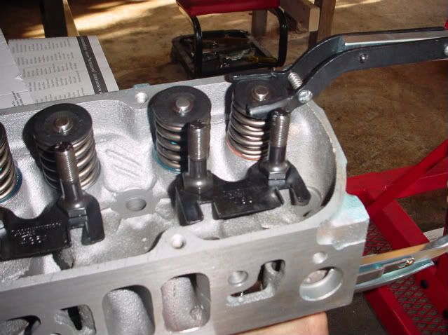 Now that the lower end was buttoned up, it was time to move on to the top half of the motor. The machine shop built the heads, so there was nothing for us to do. However, we decided to check for piston-to-valve clearance. We didn't expect a problem given that we were using stock parts. But, since these stock parts were never actually installed together by the factory, we thought it was better to be safe than sorry. In this picture we are removing the valve springs on the driver's side head so we can install the light weight check springs. The use of the light weight springs allowed us to use the stock hydraulic lifters in the valve train mockup. If you use the regular weight springs, you must use a solid lifter to get accurate results. 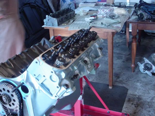 In this picture we have installed the driver's side cylinder head, complete with head gasket. After the head was bolted down, we installed the lifters, rocker arms, and push rods for the number 1 cylinder. No preload is necessary here, so we just adjusted the valve train for zero lash. You can see the light checking springs on the number one cylinder. What you can't see is the clay that we put on top of the piston in areas where there was potential for piston-to-valve interference. If you noticed that the water pump studs are threaded into the upper holes instead of the middle holes where they belong, you are correct. We fixed this later. 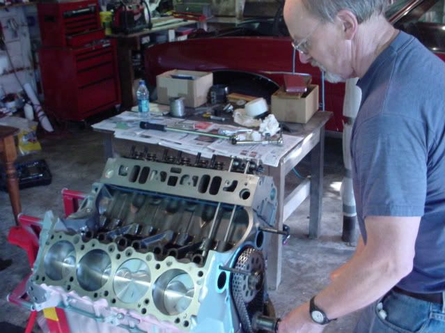 With the cylinder head, valve train, and clay in place, it was time to roll the engine over. It needs to be rolled over twice to make sure both valves have the chance to come as close as they can come to the piston. 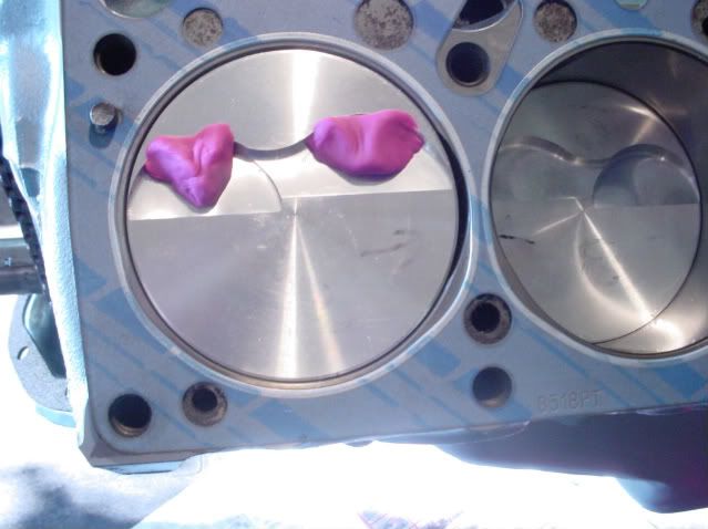 In this picture we have removed the valve train and the head. If there been a potential for interference, we would have found indentations in the clay from the valves. In this case, you can see that we plenty of clearance, because the valves never even touched the clay. Had this been a close call, we would've done all eight cylinders. 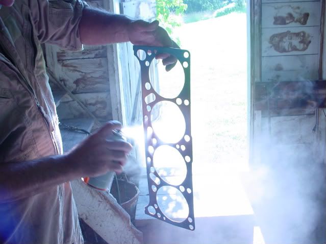 Now we that we are confident that the valve train would not be hitting anything, we installed the heads. In this photo Karl is treating the head gasket with a copper coating. This is done to improve head to block seal. 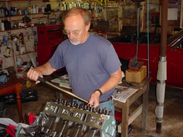 Once the head is properly placed on the head gasket and is lined up properly with the dowel pins in the block, it was time to torque the head bolts. I didn't talk about torque earlier, but the practice is to "torque in thirds", meaning that you would do all the bolts to one third of the final torque spec, start over and tighten the bolts to two thirds of the final torque spec, and finally torque all the bolts to the final spec. Rebuilding guides will show you the proper sequence for tightening the bolts. Unlike small block Fords, none of the head bolts enter coolant passages so no thread sealant is needed. However, dont forget to use 30wt motor oil on the threads of the head bolts, and be sure to put a drop of oil under the head of the bolts as well. 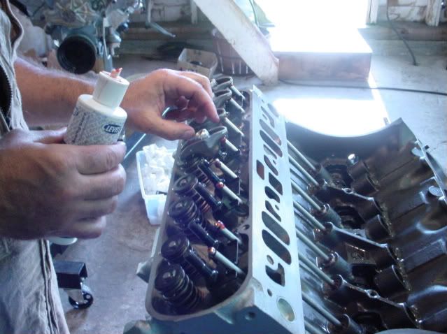 In this picture Karl is installing the valve train. The unbreakable rule is no metal to metal contact. Everything has to be lubricated with the correct lubrication. He is using assembly lube for the pushrod to rocker arm contact point. 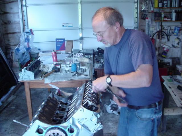 One change we made to the original valve train was to swap over to big block chevy rocker arm studs. Since we did so, it meant we had to adjust the preload on the valve train. (If you are rebuilding a Pontiac V-8 with stock components, you simply tighten the locknuts to the correct torque value.) In order to set the preload for what is now an adjustable valve train, the valve you're working on has to be on the base circle of the cam. Once this is the case, you can tighten the locknut until there is no more slack in the valve train. This is known as zero lash. When zero lash is reached, take one more half turn on the locknut. This will provide enough preload for the valve train to operate properly.
__________________
"Pay no attention to the planet Mopar. It is a strange and confusing place." ~Chiphead |
|
#19
02-03-2010, 12:36 AM
|
||||
|
||||
|
When checking valve to piston clearance, I like to either completely bottom out the pushrod in the lifter, or use a solid lifter at zero lash. Hydraulic lifters collapse very easily if they are new ones right out of the box, even the checking springs can push the plunger down and throw off the readings.
We seldom check valve to piston clearance unless the cam is a really high lift, long duration solid roller. The small hydraulic cams aren't going to have the valves close to the pistons, so it's an added step that really isn't needed for mild builds. If and when we check the clearance, it's done with no head gaskets, and the valve lash at zero. This way we automatically know that we have .039" plus .022" (.061" for example) if the engine turns thru freely without valve to piston interference. Good idea as shown to adjust lifter preload before installing the valley pan. It's easy to screw this up and not get on the base circle of the camshaft. I alway like to look right at the cam to see that the lifter is well on the base circle when I set the pre-load. Following the firing order, or going by the 180 degree set 8, then 180 set 8 more method is fine, but it's easy to miss one, or get confused, etc. There is no confusion when you are looking right at the lobe and make sure it's close to 180 degrees from the lifter when setting them.....Cliff
__________________
If you can read this, thank a teacher. If you can read this in English, thank a Veteran! https://cliffshighperformance.com/ 73 Ventura, SOLD 455, 3740lbs, 11.30's at 120mph, 1977 Pontiac Q-jet, HO intake, HEI, 10" converter, 3.42 gears, DOT's, 7.20's at 96mph and still WAY under the roll bar rule. Best ET to date 7.18 at 97MPH (1/8th mile), |
|
#20
02-03-2010, 12:58 AM
|
||||
|
||||
|
could you cover all the oil gallery plugs and freeze plugs also .i feel thats one area of info tech that is lacking , for most pontiac owners , myself included.thanks
__________________
CAROLYN JONES(1930-1983 Actress)may she never be forgotten!! |
| Reply |
|
|
The PY Online Forums is the largest online gathering of Pontiac enthusiasts anywhere in the world. Founded in 1991, it was also the first online forum for people to gather and talk about their Pontiacs. Since then, it has become the mecca of Pontiac technical data and knowledge that no other place can surpass.


 Linear Mode

