OK, Here are the pics, the first pic shows the crank hub, this is bolted onto the crack with that big crank bolt in the center.
The next picture shows the order which everything goes together, from right to left, you have the crank pulley, than the ring which fits inside the crank pulley, than the balancer which fits inside the crank pulley an sits on top of the ring, than you have 6 bolts to go through the balancer, ring, and pulley and screw into the crank hub.
Hope this helps
Mark
__________________
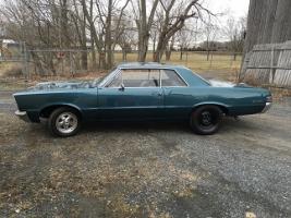
1965 GTO: 467 (Built By Dan Willever), 400 Block, Eagle 4.25 Stroke, Eagle 6.8 Rods, BRC Pistons, Custom Grind Hydraulic Roller Cam, Edelbrock 72cc Heads Ported, HS Rockers, Doug's Headers, Edelbrock Victor 4150, QTF 850 Carb, AutoGear M22 4 Speed, SPEC Clutch and Pressure Plate, 12 Bolt 3:73 Posi.
|