| FAQ |
| Members List |
| Social Groups |
| Calendar |
| Search |
| Today's Posts |
![]() |
|
| Non Pontiac Motors in Pontiacs includes factory 403,305,350 Chevy, Buick V6, Also Pontiac Motors in non-Pontiacs! |
| Reply |
|
|
Thread Tools | Display Modes |
|
|
|
#1
|
||||
|
||||
|
Eric,
Rack & pinion steering is definitely not going to be part of this build, I'm already tapped-out with all of the unplanned upgrades I've made to the brakes and suspension. I have a nice Lee 12.7:1 power steering box in the car that's 20 years old and still going strong. I was already having issues with the deep backspacing on the 18X9" front wheels, the rim was hitting the rearmost tube on the Hotchkis upper control arms near full steering lock. I bought the SPC adjustable uppers to gain some clearance there (straight adjuster vs outward curved tube) and it just sort of snowballed into a complete front end upgrade. The limited turning radius won't be any big deal. It was already reduced with the B-body spindles with their longer steering arms (I hardly noticed the reduced radius), the new ATS spindles will give me some turning radius back so it's probably a wash. Having the tierod end (grease zerk removed, a plug in there instead) touch the pan once in a while won't hurt it. If the new SPC upper arms don't have enough clearance to prevent the rim from rubbing, the limited travel of the centerlink will. ![]() Bart |
|
#2
|
||||
|
||||
|
.....and took another step forward. The weather cooled down into the mid to low 90s today, last weekend it was close to 110 degrees
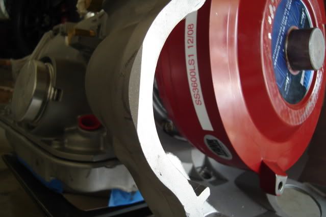
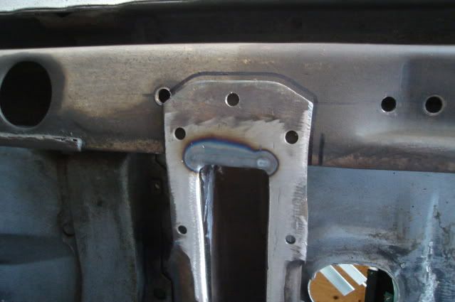
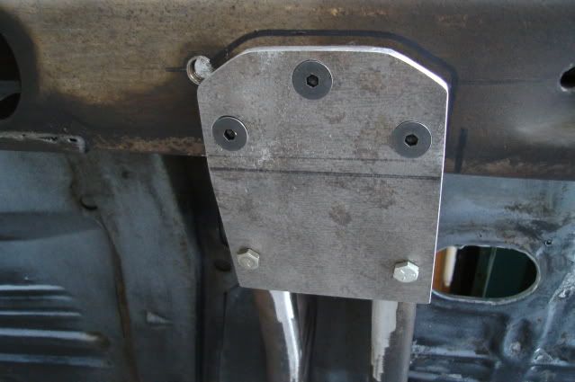
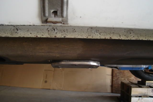
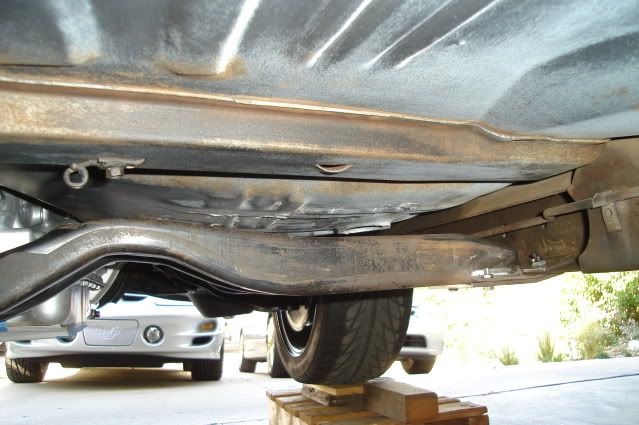
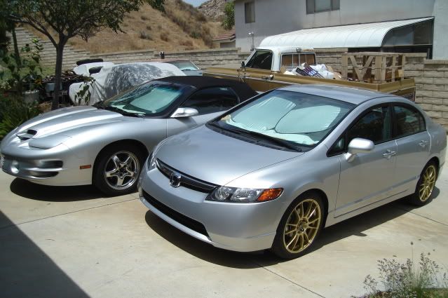
and just too hot to do anything. I put the Tempest up high on small wooden pallets once again and removed the passenger side header. The headers need to be out of the way so I can remove the lower control arm bolts, a complete front suspension upgrade is my next task. While doing some fitting and checking I found that with the transmission bellhousing just barely touched one of the passenger side header tubes right where the starter goes. I knocked off the corner of the bellhousing with a large flat file to give the header tube some clearance. ![]() Next I bolted the trans up to the engine. I bolted the finished trans crossmember to the trans mount and jacked it up tight against the bottom of the frame. ![]() After drilling three 5/16" holes in each side of the frame using the crossmember holes as a guide I bolted the trans crossmember in place using the upper and lower reinforcement plates I made previously. ![]() The crossmember and lower reinforcement plate hang a little over 5/16" below the bottom of the frame rail. ![]() Right above the exhaust clearance hump you can just get your finger between the top of the crossmember and the floorpan, about 1/2" to 5/8" of clearance. ![]() Finally, I would like to thank my two daily drivers for their patience, putting up with numerous cold starts when they're getting moved around and for braving the hot sun all day whenever the Tempest is getting attention. They're both very spoiled and really hate sitting outside.![]() Now there is finally enough weight over the front end to start to compress the springs, the added weight of the 4L70E trans got the front suspension off of the upper bump stops. Next up is all of the front suspension and brake work, stay tuned. |
|
#3
|
||||
|
||||
|
.....by removing all of the old front end components.
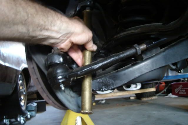
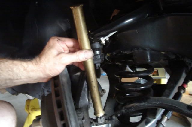
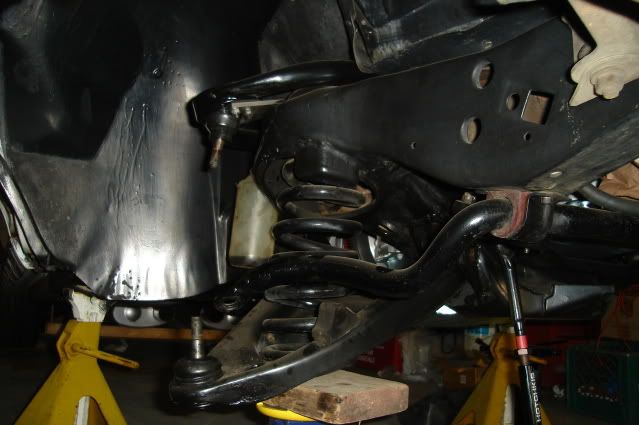
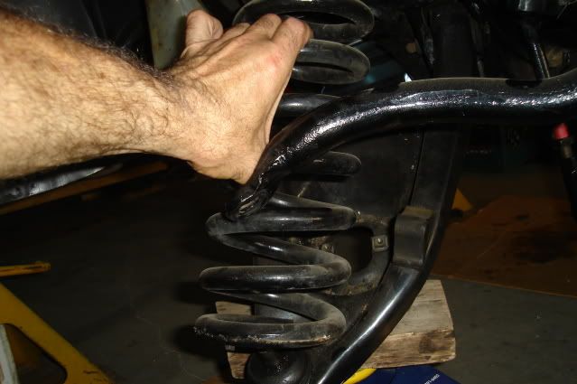
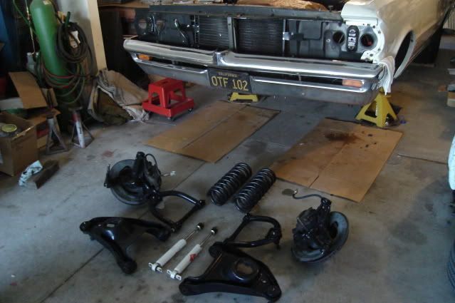
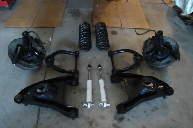
I put the Tempest up on two large 6-ton jackstands and removed the wheels, then removed both front shocks and the sway bar end links. Next I loosened up the tie rod adjusters, but left the tie rods attached for now so they would help keep the spindles from moving while loosening up all 4 of the ball joint castle nuts. After removing the cotter pins and loosening the ball joint castle nuts by a few turns I used a 12" long by 1" diameter brass bar as a drift to knock them loose from the tapered holes in the spindle. After only a couple of hard raps on the ball joint studs with a 2-pound hammer they popped right out of the spindle, against the loosened castle nut. The brass bar is long enough to do all of your hammering clear of the suspension parts, plus you can get a good swing with the hammer. ![]() ![]() Next I put my floor jack with a 2X6 wood block underneath the control arm spring pocket and jacked it up enough to remove the tension against the castle nuts. After removing the castle nuts I let the jack down just enough to get the spindle assembly out, I disconnected the brake hose at the frame bracket beforehand. ![]() The H-O Racing front springs are fairly short and came out easily after letting the lower control arms all the way down with the jack, I didn't need to use a spring compressor. Having enough weight on the front end is the key to getting away without the need for a spring compressor, along with a short free-height spring. ![]() To get the upper control arms off I had to remove the rubber spash shields from the inner fenders to get enough room to manuever them out. I also had to take the steering shaft loose from the rag joint coupler on the driver's side and push the steering shaft over as far as possible to get the control arm shaft off the 2 mounting bolts that are pressed into the frame. Tear down is now complete, all I need to do now is a little cleaning of the suspension attachment points on the frame and I'll be ready to start installing the new parts. ![]() There's really nothing wrong with the old '78 B-body spindles with 12" rotors, reinforced stock lower A-arms and Hotchkis upper control arms with greasable poly bushings. They truly made a night and day difference in braking and handling over the original factory 9.5" drum brakes and rubber-bushed suspension pieces that had over 140K miles on them. ![]() I'm replacing them all now with SPC adjustable upper control arms and tubular lowers, American Touring Specialties AFX forged aluminum spindles and C6 Z06 brakes with hopes that I'll see yet another night and day difference in braking and handling. This is really going to be a fun canyon carver.
|
| Reply |
| Thread Tools | |
| Display Modes | |
|
|