


| FAQ |
| Members List |
| Social Groups |
| Calendar |
| Search |
| Today's Posts |
|
#1
 11-30-2017, 03:52 PM
|
|||
|
|||
|
I have the original pump motor and top cylinders in my GTO.
I was expecting to have them rebuilt/restored. I've been told that Hydro-E-Lectric doesn't rebuild them, I had assumed they did. Has everybody else just gone with new replacements or is there somebody out there that does a nice job rebuilding the original components? Also, on my top mechanism, there is what I believe would be called a rivet, rather large at a hinge joint. On one side, this rivet is gone and had been replaced by a bolt. Are repair parts available for this rivet (or whatever the piece is) and how easy/difficult is it to replace? |
|
#2
11-30-2017, 05:55 PM
|
|||
|
|||
|
I had my pump rebuilt from my 64 tempest. It had a bad winding in the armature. I found a contact to an old guy in California I think. He wound them by hand. Its doing the job and working well. I did this to save a little money.
I can't see any reason to try and have the hydraulics rebuilt. The ones that Hydro sell are very nice and near identical. They also sell exact style lines too. The old lines just get old and brittle. The hydraulics just plain wear out too. I do not know of anyone that sells replacement rivets for the frame rails. Even if you were able to get one how would you install it? There might be some ways to get creative with a bushing and a button head bolt to make it look nicer but I would think your best bet would be sourcing out a new frame rail. I had to do this with my Conv FB. |
|
#3
12-13-2017, 04:18 AM
|
|||
|
|||
|
...that's all i did to 'cure' my old 64 lemans tops hydraulic pistons from leaking...must pry off the seal carefully, remove packing, then replace rubber O-ring...and re-pack and bend seal back down over packing...that was twenty years ago..knock on wood..still not leaking...the motor i replaced with new hydro E unit...
|
|
#4
12-13-2017, 06:37 PM
|
||||
|
||||
|
John I've repaired my own pumps . There used to be a thread on here about repacking the cylinders. Send me a picture of what you need I have a 64 top frame here I've been using for parts .
__________________
"America will never be destroyed from the outside. If we falter and lose our freedoms, it will be because we destroyed ourselves." Abraham Lincoln "A free people ought not only to be armed and disciplined, but they should have sufficient arms and ammunition to maintain a status of independence from any who might attempt to abuse them, which would include their own government." George Washington 
|
|
#5
05-16-2018, 06:37 PM
|
|||
|
|||
|
Okay, I went with new cylinders.
I "restored" the motor myself. It was dead to the world, took it apart and cleaned out all of the tan colored crumbly crud. Anybody know what causes that crud? The crud caused one of the brushes to stick which is why I figure it wouldn't run. After I got the motor back together, it runs sweet. Haven't installed the reservoir yet, so don't know if it will hold fluid but I'm hopeful. Learned a lot while doing it. I used paint to mimic the gold dichromate cad look on the two outer ends and silver grey in the middle. I think it looks very nice. Anyway, I realized I didn't have a good pic of the motor before I removed it 25+ years ago. I want to be sure I am orienting it properly. Attached is the only pic I took back then, it shows how the ground wire is attached. This is looking from over the back seat area toward the rear of the car so the ground wire is to the driver side. You can see I have the motor matched to the metal cover (different motor p/n was used with the cardboard cover that I believe came later in the year). Based on this pic, I'm pretty sure the motor end is on the driver side and the reservoir end with fill plug is on the passenger side. Does that check out with everybody else? |
|
#6
05-20-2018, 01:15 AM
|
||||
|
||||
|
On my car the electrical side faces towards the driver's side of the car and the yellow cad plated liquid chamber faces the Passenger side.
__________________
Peter Serio Owner, Precision Pontiac Last edited by Peter Serio; 05-20-2018 at 01:16 AM. Reason: added a photo |
|
#7
05-20-2018, 08:29 AM
|
|||
|
|||
|
Plating over paint.for me. wet sanded the pump housing then polished. Plated the reservoir yellow cad and the end cap silver zinc. on the end cap you gotta drill out the brush holder rivets and tape the bearing up before plating. used stainless screws with the head sanded and polished to look like the rivet head. and it's all hidden behind the pump shield
|
|
#8
05-20-2018, 03:50 PM
|
||||
|
||||
|
I'll add this: I had to overhaul the electric top motor on my '67 about 3 times the first 4 or 5 years I had the car. The impeller would sieze from corrosion caused by the brake fluid absorbing water. After the 3rd time, I flushed the brake fluid out of the system, and installed ATF. That was almost 30 years ago. No issues yet! Use ATF, not the factory fill brake fluid. As a side note, Hydro Electric overhauled my rams.....$90 each in 1985. But they still are leak free.
__________________
Jeff 
|
|
#9
05-22-2018, 02:12 PM
|
||||
|
||||
|
Brake fluid = bad. ATF = good! They sell new "O" ring kits to rebuild those pump motors.
My original rams were crimped at the top end, the tube part is made from thick aluminum. My old ones were frozen in place from the brake fluid sitting for 30+ years. I decided to just buy a pair of brand new ones. I rebuilt my pump motor and put in fresh ATF. The new rams work great!!
__________________
Peter Serio Owner, Precision Pontiac Last edited by Peter Serio; 05-22-2018 at 02:27 PM. Reason: added a photo |
|
#10
05-22-2018, 06:13 PM
|
|||
|
|||
|
I has heard others using clear power steering fluid which is basically transmission fluid. If by any chance you get a leak there's no blood read fluid to clean up.
|
|
#11
05-22-2018, 06:38 PM
|
||||
|
||||
|
Speaking of ATF vs brake fluid, what years had what fluid from the factory? I know the '66 Fisher Body Manual calls for brake fluid.
When restoring the hydraulic system and reusing parts, you need to be sure what you have since it can't do the seals any good to mix those fluids. |
|
#12
05-22-2018, 07:21 PM
|
||||
|
||||
|
I think 1967 was the changeover or transition year from BF to ATF. I always thought it was a dumb idea for GM to run brake fluid in hydraulic top systems but I am sure that they bought brake fluid by the railroad car tanker full. They probably had a TONS of brake fluid available and just used it that way. The scary thing was if a line ever popped or leaked you've got a big brake fluid mess all over the place and worst luck to the person if any of that ever got splashed onto an exterior painted surface of the car! Quarter panel or deck lid.
__________________
Peter Serio Owner, Precision Pontiac Last edited by Peter Serio; 05-22-2018 at 07:22 PM. Reason: spelling. |
|
#13
05-24-2018, 12:15 AM
|
|||
|
|||
|
I spoke with a rep from Warren Petroleum today, they still make Type-A ATF but if you want something without the red dye use R&O 10 WT hydraulic oil. The rep said it was the same thing as Type-A ATF without the red dye.
|
|
#14
05-25-2018, 02:09 PM
|
|||
|
|||
|
Thx for the info on the orientation question.
8LUG, that looks sweet. I chose not to plate after realizing I would have to drill out those rivets. Coupled with not being sure it would run when I was finished, I went with paint. I will post pix when I finish the reassembly. I painted mine "gold cad" on both ends. The reservoir end was clearly gold cad. I wasn't sure about the motor end. But after a cleaning and when I had it in good light, it definitely showed a gold cad "tone" (hint of goldish with slight red and green hues). Maybe somebody knows for sure that it wasn't gold but seemed logical to me that Delco would have plated both pieces the same. Then again, I have no idea why the reservoir end retained the gold cad so well but the motor end didn't. I tried hand polishing the aluminum(?) center section that contains the permanent magnets. But I couldn't get it uniformly clean enough by hand and didn't have a buffer to do it by machine. I tried to just clear it hoping it would look okay but it didn't so I painted it. I probably could have used a more silvery color to better mimic the unplated metal. The whole thing may not look "correct" but it does look nice. Just hope it doesn't leak and generates the needed pressure once installed. Fingers crossed. I read on a Cadillac forum that ATF should not be used for hydraulic top motors prior to '53 unless you change out the hoses, etc. '53 up you could use ATF but I'm guessing GM continued to recommend the Brake Fluid to avoid confusion and misuse of ATF on the older models. And apparently they did so for quite a number of years. My '64 Tempest Shop Manual advised to use "Delco No. 11 Hydraulic Fluid (GM Hydraulic Brake Fluid Super No. 11, or its equivalent)". I have to assume the Delco Hydraulic Fluid was the same as the GM Brake Fluid. The No. 11 Brake Fluid designation apparently has continued in use (at some point the "Super" designation has been changed to "Supreme") and despite GM's apparent desire to make it seem "special", the No. 11 is same as DOT 3 Brake Fluid by all accounts. They had earlier specs, I saw a reference to GM Brake Fluid No. 9 in my search. Given that the '64 trunk interior is painted Body color, I like the idea of using ATF. Curiously, I recall red fluid leaking from the hoses when I pulled the top motor 25 years ago. Of course, even if I am remembering correctly, no way for me to know if that was evidence of the original fluid or if it had been serviced sometime in the previous 30 years. They do sell "rebuild" kits but I have to say I was disappointed by what I received. The reservoir perimeter to pump used a molded seal. I'm sure you could use the large O-ring that came in the kit, but the seal makes more sense to me. Likewise, the kit contains an O-ring for under the washer for the center reservoir to pump bolt. The original washer includes a formed seal as does the original screw-in fill plug. The kit includes a rubber fill plug, nothing for the screw-in fill plug that is original to mine. My seals are pliable enough for reuse so I won't be using the bolt O-ring or the rubber fill plug. The kit included O-rings for the two hose port connections on the center section. The originals are SQUARE-rings. Again, the O-rings probably will work but I picked up Square-rings from a local hydraulic service shop and will use them. Square-rings are circular but have a square cross section versus the round cross section of the O-rings. I figure if Delco thought they should use Square-rings, I would go with that. The kit also includes a 3rd small O-ring for the end of the armature shaft (under the pump gear). I carelessly damaged the original and can't quite tell if this one was originally a Square-ring also or an O-ring. Since it was the same size as the ones for the hose ports, I'm guessing it was also a Square-ring so I plan to assemble it with one of those. The kit does include new pump ball bearings and the rubber feet which I will use, so the kit was not completely a waste. I have another install question but will post it separately so it doesn't get lost in this lengthy post. |
|
#15
05-25-2018, 02:18 PM
|
|||
|
|||
|
So now I know the correct orientation of the motor.
But nobody thought to check the routing of the hoses to the cylinders before removing them so I am being asked to determine how the hoses are routed. Anybody with good pix to show the correct hose routing? This is for a '64. I especially need to see from the cylinders back but all the way to the motor would be great. Both sides or either side will help. |
|
#16
05-29-2018, 12:09 PM
|
|||
|
|||
|
Still need help for the hose routing.
Anybody? |
|
#17
05-29-2018, 12:21 PM
|
|||
|
|||
|
Quote:
|
|
#18
05-29-2018, 12:40 PM
|
|||
|
|||
|
John,
I think this is what you need. Hope you can see them. 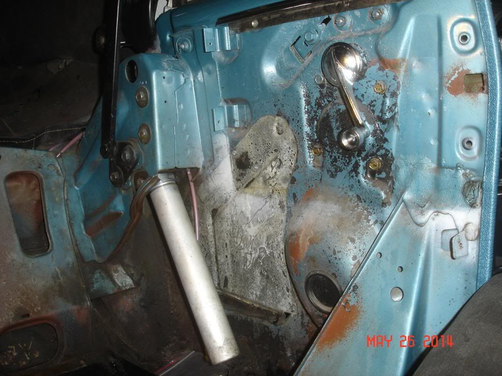 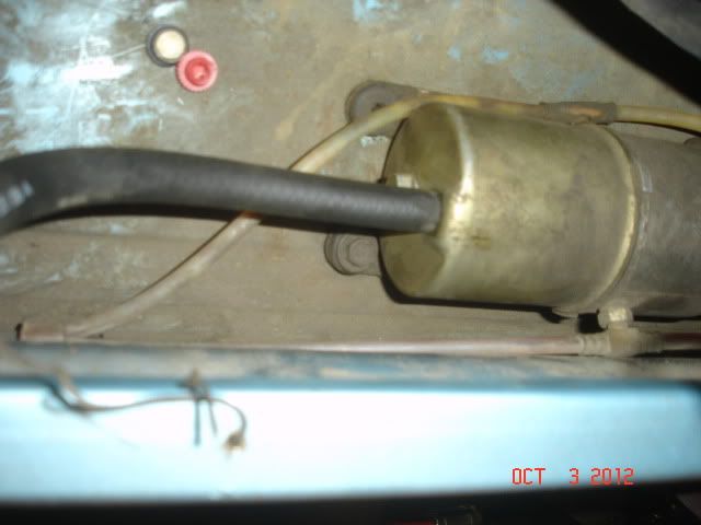  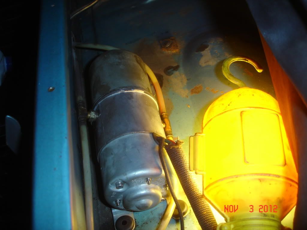 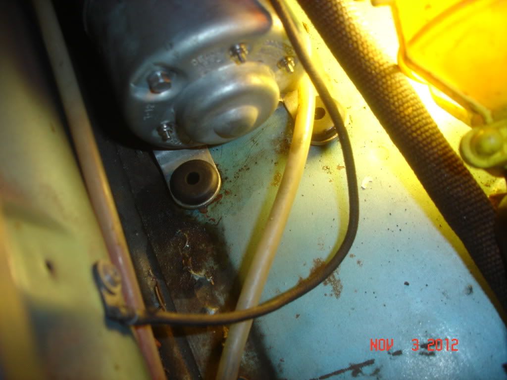 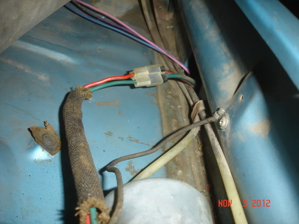 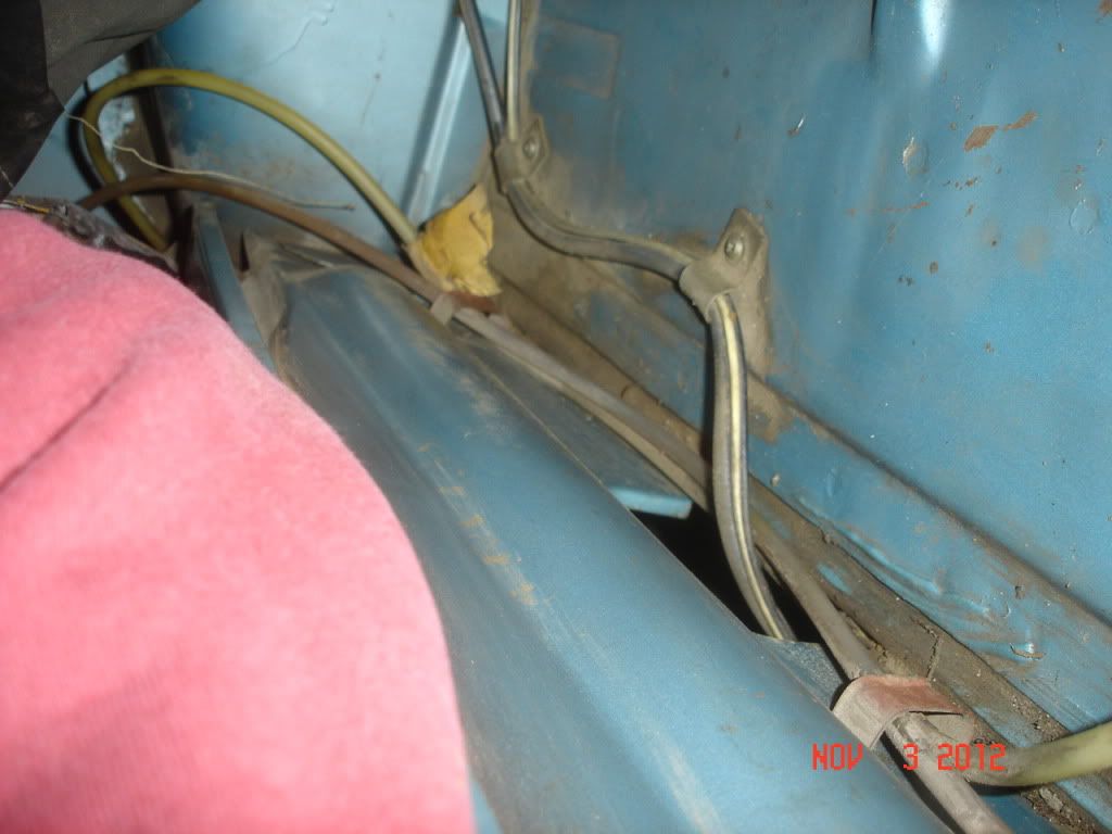
|
|
#19
05-29-2018, 05:00 PM
|
|||
|
|||
|
rohrt, thanks, those are perfect!
One comment, looks like you had motor p/n 5044586 with the "foundation board pump shield". Mine got motor p/n 5044573 with the "steel pump shield". On mine, the ground wire was attached at a screw securing one end of the shield. Yours looks to have been secured to a hole in the sheetmetal behind the back seat. Also, it took me a little while to realize that your wiring comes out of the grommet on the motor oriented toward the front. Mine is oriented toward the rear. Looking at the motor from the end, yours is about at the 2 o'clock position. Mine is about at the 10 o'clock position. I also notice that the fluid ports on your motor are oriented differently. Your rear port is at about 10 o'clock, the front port at about 4 o'clock when viewed from the same motor end. My rear port is about at 8 o'clock and the front port is at about 2 o'clock. This will be more obvious when I post pix of my completed motor. Pix are stuck in my camera at the moment, lost the USB wire and had to order a new one so I can download them to my computer. |
|
#20
05-30-2018, 09:23 AM
|
|||
|
|||
|
Quote:
That is correct. You can still see some of the cardboard under the screw. Who got the metal ones? Based on assembly location? Do you think based on what you know the motor may not be original? I had no reason to think it was not original. Every piece was completely shot. 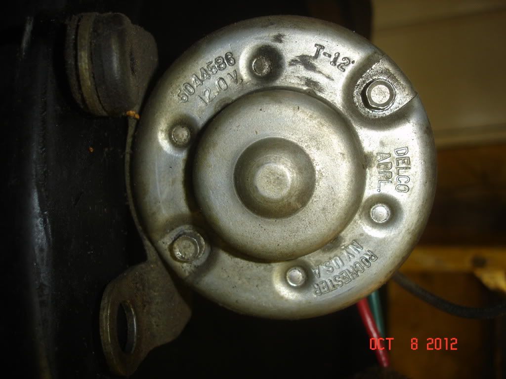
|
| Reply |
| Thread Tools | |
| Display Modes | |
|
|
The PY Online Forums is the largest online gathering of Pontiac enthusiasts anywhere in the world. Founded in 1991, it was also the first online forum for people to gather and talk about their Pontiacs. Since then, it has become the mecca of Pontiac technical data and knowledge that no other place can surpass.


 Linear Mode

