


| FAQ |
| Members List |
| Social Groups |
| Calendar |
| Search |
| Today's Posts |
|
|
|
#1
 05-27-2022, 11:39 PM
|
||||
|
||||

Work has been insane lately trying to keep up. Today I had a bit of time so decided to pop the motor in with the harness loose and then decide where what needs to go. The harness and programmed ECU was supplied by SwapTime out of Las Vegas.
As you see it is quite roomy in the back - the trans/engine split line is as stock. The mounts work superbly - went right in as designed. I cannot attach the file here, but anyone who wishes them I will send to, then you can have them cut. |
|
#2
05-28-2022, 11:42 PM
|
||||
|
||||
|
More time today. I decided to stab in the trans to check fitment and gear up to fab the crossmember mounts. One thing that always bugged me was transmissions are never flat on the bottom - always rolling about. I flipped the TKX on it's top and took a hard look. I noted that 2 of the lower bolts could be made to hold a "base" so to speak, so a few minutes of fab work and this is what I got:
Sits on some stacked milk crates atop a rolly cart just fine - quite stable. I ran the vehicle lift all the way up,then laid the trans on it and rolled it under the car - then lowered the car. Slid in perfectly - hopefully she is just as trampy when the clutch and other components are in place. I was able to reuse the stock trans support and mounts - fit in perfectly, The rear mount will need a 1/2 - 3/4" shim to get to the proper driveline angle and one corner of the shifter porch will need a quick visit from the singlejack to clear the shifter mount. All in all not a bad day, though the shifter shows signs of being a real bugger. Hurst makes a shifter called the Sidewinder that would have solved this but requires machining to the tailhousing to work. 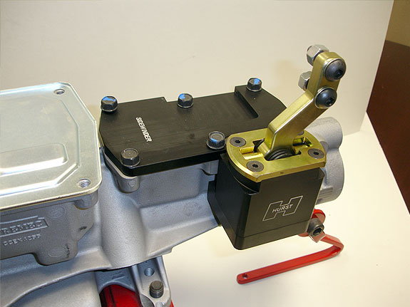 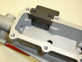 Last edited by Scarebird; 05-28-2022 at 11:49 PM. |
|
#3
06-12-2022, 11:24 PM
|
||||
|
||||
|
Time to fit a driveshaft.
I raised the car as high as it will go on the lift, then put an exhaust stand under the differential and lowered the car till the lift engaged the locks. I then used the screw feature on the stand to raise the rear till the frame barely came off the rear lift arms. My lift is also firmly tied into the roof structure so no danger of the lift pulling out of the concrete. I measured the centerline of the bearing cap surfaces and subtracted an inch for install then cut my existing driveshaft in the lathe with a parting tool. I then mounted the section with the yoke intending to carefully whittle away the tube and reuse the yoke. Wrong. The section was not held firm enough and popped out when I got greedy with the cut depth. It hit the tool post and scratched the yoke in the thinnest section. Dammit. Luckily one of the local driveshaft shops had a yoke for a fair price ($40) I needed to trim the insert section of it about 0.016" to get a slight interference fit. This time I mounted it first in the lathe, drilled a centering hole and used that to retain the yoke. Uneventful this time. Most shops use a MIG gun to weld up the yokes, I elected to Heliarc it for good penetration and low bead. Fitted up to the car revealed good results - good engagement length and removal ease. Last edited by Scarebird; 06-12-2022 at 11:42 PM. |
|
#4
06-12-2022, 11:40 PM
|
||||
|
||||
|
Now that was finished, time to check the driveline angles.
I made a big protractor from a AutoCAD drawn file (available to who wants a copy), printed it out and spray glued it to a piece of foamboard - carefully cutting out the right angle edges. A piece of 0.063 welding rod made a nice pointer. With the rear suspension at ride height I got the following data: Engine / shaft angle: 2° Shaft / Diff angle: 5° It looks like I will need to drop the tail of the trans 1.5° to split the difference. Not an issue as the shifter mounting plate is almost touching the floor pan. One thing that does bother me is the engine and diff are not parallel at all: 5° difference. I will need to see if this is an issue. |
|
#5
06-13-2022, 08:58 AM
|
|||
|
|||
|
Quote:
|
| Reply |
| Thread Tools | |
| Display Modes | |
|
|
The PY Online Forums is the largest online gathering of Pontiac enthusiasts anywhere in the world. Founded in 1991, it was also the first online forum for people to gather and talk about their Pontiacs. Since then, it has become the mecca of Pontiac technical data and knowledge that no other place can surpass.




 Hybrid Mode
