


| FAQ |
| Members List |
| Social Groups |
| Calendar |
| Search |
| Today's Posts |
|
#221
 05-09-2009, 08:08 PM
|
||||
|
||||

Quote:
As for racing, I am up for it. I think it would be very close. B-man might get you if he gets his suspension dialed in. I bet his car will be only about 3300 pounds, compared to my 3700. Andrew |
|
#222
05-09-2009, 08:40 PM
|
||||
|
||||
|
Quote:
I'm hoping my car weighs in at 3600 when I'm done, and I'm not willing to bet it will be that light. It weighed in at 3780 with 3/4s of a tank of fuel and a big ice cooler in the trunk at my local drag strip before I started this reincarnation. That included an all-iron 455 with Tri-Power and Ram Air exhaust manifolds, the intake and carbs alone weigh close to 80 #. This powerplant had to be close to 675 to 700# alone, so I figure I'm saving about 250 # with the new LS3. But my new 4L70E will weigh more than the old TH400. The new 9.5" YANK converter will be lighter than the 13" Continental I had though so it's close to a wash there with my bet still being the OD trans package will add weight. My old 17X8" wheels were 37# each bare, my new alloy 18X9" wheels are 20.8# each. So with all 5 wheels accounted for I'm dropping 81#, but I'm easily adding just about all that back if not more with the monsterous Z06 rotors and calipers all around. So that's a wash. I'll be saving some weight up front with the aluminum ATS spindles & steering arms and tubular SPC lower A-arms and adjustable uppers, but no more than 20# in my estimation. The new rear suspension parts will drop a few pounds and I'm going to a smaller rear sway bar (1" vs 1-3/8"), but the heavier 8.5" rear replacing the 8.2" one should even out the score there some. The addition of the new Classic Auto Air 'Perfect Fit' system that I finally ordered a few days ago will easily add another 70+ pounds, I'm guessing some new Second Skin floor insulation will add 20 to 40 more compared to the old original stuff. But I'll be dropping weight mainly from the front of the car, and most of any additional weight added from the various components will be fairly evenly distributed front to back and even help lower my center of gravity a little. Quote:
When I get into the wiring of this beast it will really test my skills and patience as I'm really not an electronics guy. I'm really just learning as I go, and so I far I've learned this is project is getting to be very expensive.  Quote:
  Quote:
Bart |
|
#223
05-09-2009, 11:39 PM
|
||||
|
||||
|
Picked up some more items.....
.....to pretty much finish off the suspension upgrades, a new $300 set of Bilstein Heavy-Duty gas shocks. These are supposed to be one of the best riding and handling shocks available for a reasonable price, by just looking at them the German quality is clearly evident.
I really couldn't justify the purchase of single-adjustable shocks (about $700) or double-adjustable shocks (about $1500) since I'll just be doing a little agressive pleasure driving from time to time and really don't have any plans to autocross this car. Part # F4-BE3-2972-HO front and AK2080 rear. 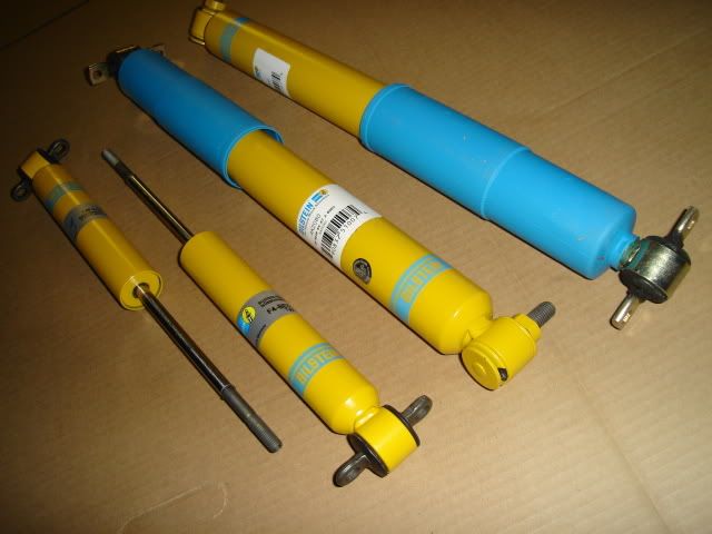 Soon the new Classic Auto Air system will arrive and it will be time to really dig into some 'real' work on the car. The new A/C system along with the Speartech harness and controller will both need to find a home under the dash and on/through the firewall. Today I finally finished off the window channel rust sanding with some 180 grit paper and tomorrow I plan to seal up the front and rear window channels with some silver POR-15. Staying motivated. 
|
|
#224
05-10-2009, 09:00 PM
|
||||
|
||||
|
Window channel repair completed!
Today I got an early start so I could complete 3 coats of POR-15 on the window channels.
I started by scrubbing the already clean channels (cleaned with Simple Green) with some Scotchbrite dipped in PPG DX-579 Metal Cleaner (same as Metalprep) to etch both the rusted areas and the clean bare metal areas as well. Then to keep the Metal Cleaner and rinse water from finding it's way down into the body I plugged off all of the trim clip screw holes with some wooden matches (of all things!) wrapped with masking tape so they would seal up the holes. I left the matches in place during the POR-15 application to keep it from plugging up or reducing the size of the holes. All of the pics were taken after the first coat of silver POR-15 was applied. 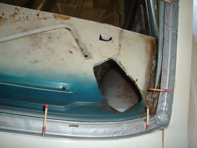 The 3 small holes on the passenger side rear window channel were patched with 2 layers of fiberglass cloth. 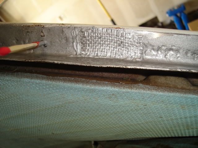 Driver's side bottom corner. 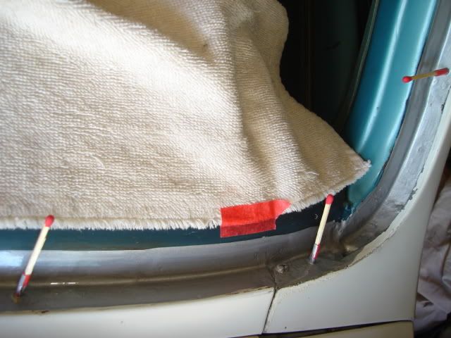 Heaviest pitting is right in front of the driver. I plan to sand this down after the POR-15 cures for about a week and put down a few more coats to level out the surface for a better seal when the new windshield is installed. 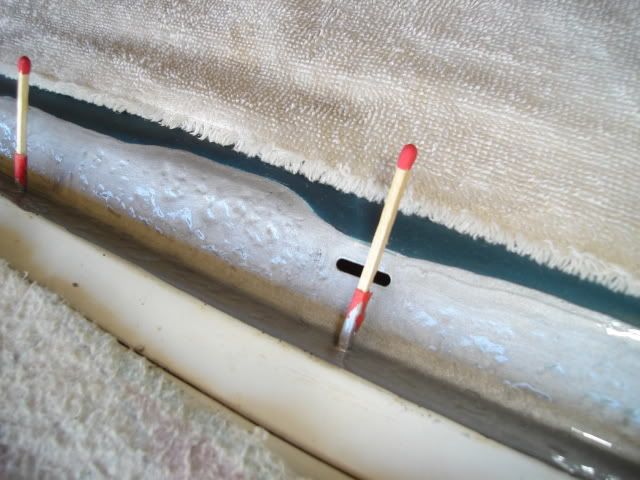 Front and rear channels with the first coat completed and waiting 2 to 3 hours for a second coat. 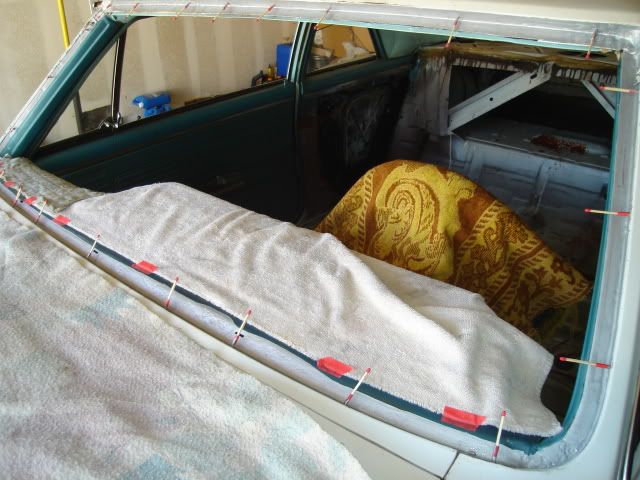 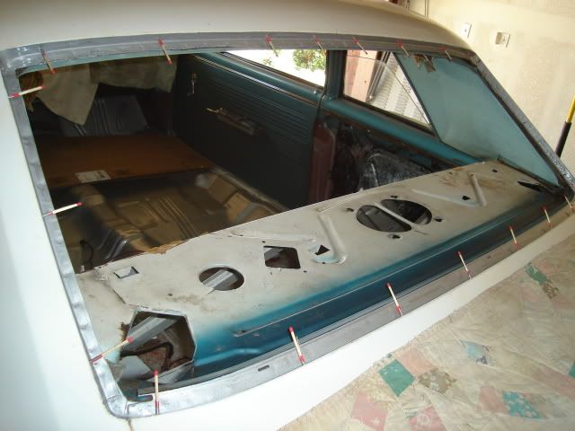 Right now it's time to put down the 3rd coat of POR-15 before the day/weekend is gone. I did call my Mom right after the second coat was down, Happy Mother's Day!
|
|
#225
05-10-2009, 11:37 PM
|
|||
|
|||
|
Quote:
The bilsteins were super aggressive and made the car handle incredible, but with the other mods they were too much. On stock springs it would have been perfect. I don't know how your model bilsteins are valved though. great shocks! |
|
#226
05-14-2009, 12:36 AM
|
||||
|
||||
|
Dashboard has now been gutted.....
.....to prepare for the Classic Auto Air air conditioning system installation. I'll need to find room to tuck the Speartech wiring harness and controller under there somewhere as well.
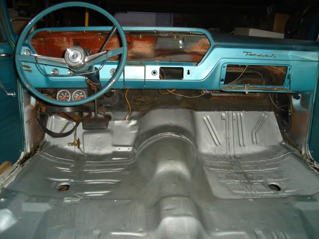 I removed the gauge cluster so I could have room to work under the dash. The cluster housing itself will be replaced with nicer one that isn't warped from sun exposure, it will also have some paint work done to freshen it up a little at the same time. 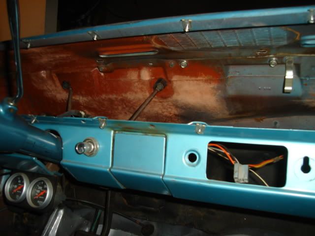 The entire factory heater box assembly and control cables on the inside of the car were removed completely as they will not be needed, the aftermarket A/C unit has both the heater core and A/C evaporator incorporated into a single unit. The only thing that still needs to come out is the old factory firewall pad and insulation that will be replaced with modern insulation from Second Skin. While I have access I'll put insulation on every surface under the dash and on the firewall that I can reach. 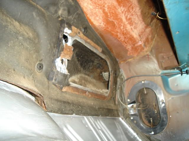 The heater and A/C evaporator main unit is shown here along with the two separate outside small A/C vents and the twin central vent, the vents mount at the bottom edge of the dash. There is a shallow plastic glovebox insert provided that mounts with the stock hardware. The size of the main unit won't allow the stock glovebox cardboard to be used, a very small sacrifice. 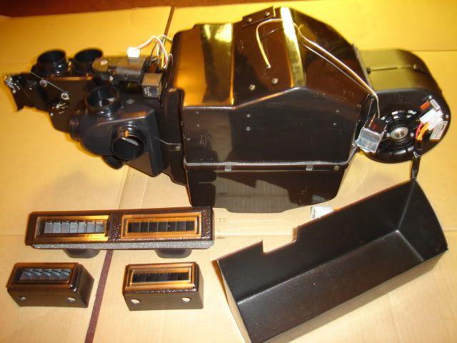 The other side of the unit that will face the firewall is shown here along with the thick composite/plastic insulated main firewall blockoff plate that comes with holes already drilled for the heater and A/C hoses to pass through. The new Sanden compressor and 2" underdash A/C and defrost ducting hose is shown here as well. 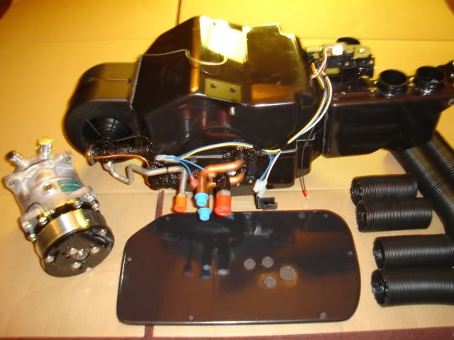 The factory heater blower motor and fan along with the stamped sheetmetal heater housing on the engine side of the firewall will be removed as well, they will be replaced with blockoff plates that are provided with the kit. The passenger side inner fender will have to come out to remove the heater housing. None of the factory heater parts will be retained with the exception of the stock heater control panel in the dash, it will be modified to accept the two new heat and A/C control cables. Keepin' on it.
|
|
#227
05-14-2009, 10:41 AM
|
||||
|
||||
 A/C tools..........
Bart,
Just a reminder: you are welcome to borrow my hose collar crimping tool if you wish. It's a lot easier than clocking the hoses, marking them, and going to a local shop to get them crimped. I might even deliver it in order to get to fondle some of the Tempest's parts.Les
__________________
Les Iden ---------------------------- '65 Buick Sport Wagon Custom, 340, T350, 3:23 '66 GTO Post/468, 700R4, 3.31 (Mike's as of 9-16) '68 Grand Prix/455, dual AFBs, T400, 2:93 posi (sold) '72 TA tribute/461, T400, 3.08, (Russ's as of 9-16) '97 Mitsubishi Eclipse Spyder Turbo, Konis, 5 speed '09 Torrent GXP, nav, Sun & Sound pkg., Bilsteins |
|
#228
05-17-2009, 12:29 AM
|
||||
|
||||
|
Tore down the front end sheetmetal today.....
.....in preparation for the A/C install. The inner fender on the passenger side needed to come out so the old heater box assembly on the firewall could be removed.
The front bumper needed to come off first, it would have to be removed to do the body mount replacement anyway. The grilles were removed as well to have access to the core support so I can mount the condensor. There are also two 1-1/4" holes that need to be cut so the A/C hoses can pass through the support to the condensor. 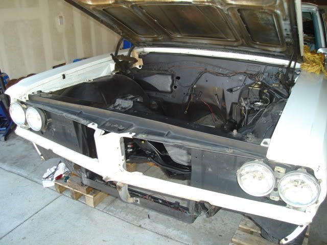 I took off the fender, even though the A/C kit instructions show it staying in place. It's easy to scratch up the paint on both the frame and inner fender trying to get it out with the fender in place. 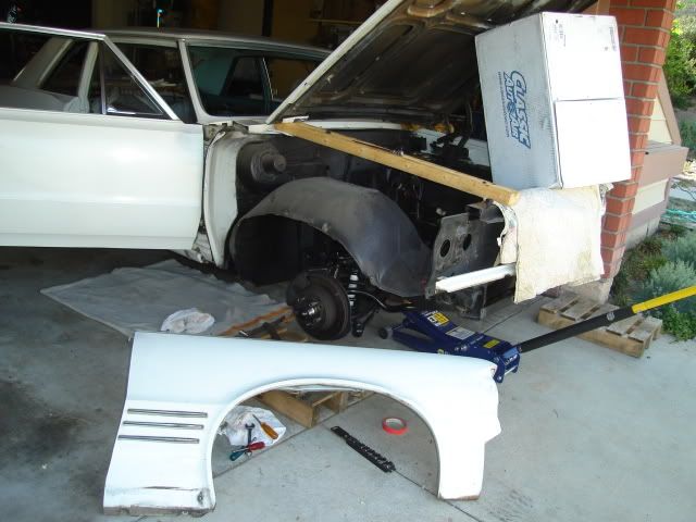 The heater box assembly came off easily by removing the last two screws that were still holding it to the firewall right next to the fan motor. The six nuts holding the rest of it down had already been removed while I was taking out the inner heater box under the dash. 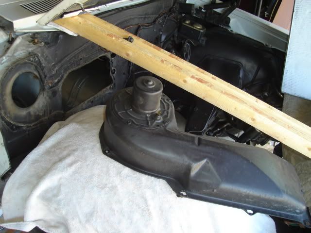 I used a putty knife to remove most of the factory sealer, the temps were in the 90s here today so the sealer was pretty soft. The remaining sealer residue came off easily using some old gasoline that I drained from the old Tempest fuel tank. 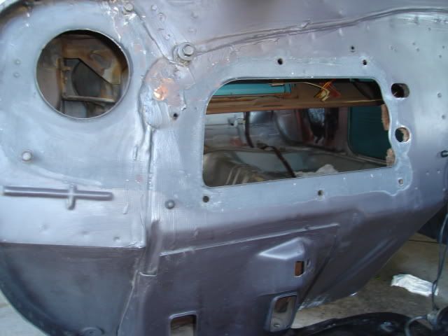 Here's the main blockoff plate that was supplied in the kit being held in place. 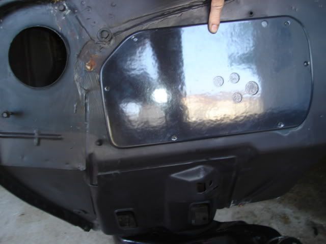 Rather than use the supplied blockoff plate for the heater blower opening I'll use this 4" hose adapter that I fabbed out of stainless steel. This way I can supply the LS3 intake with some cool air ducted from the cowl vents. The hose adapter is a piece I removed from my '64 GTO when I retired it from the dragstrip and put the stock heater assembly back in. 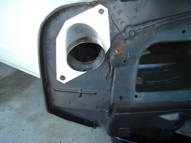 I scrounged this factory intake hose and several others like it from a self-serve boneyard about 15 years ago when the mid-70s GM cars could still be commonly found there. 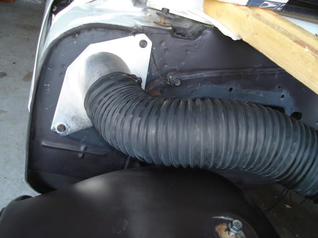 Another view of the hose adapter and intake hose. I took the opportunity to tidy up the original white paint on the cowl with a little Simple Green. Did I say this thing was cherry?  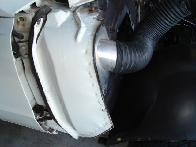 Heres a pic of the 455 HO engine in my GTO with the cool intake air from the cowl taken from two locations. The hose on the driver's side connects to another adapter that takes the place of the factory wiper motor, another thing I removed to save weight at the time. 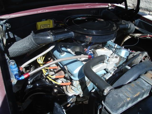 I'm looking at doing something similar with the LS3 but with only one inlet. I'm going to see if I can mount a stock '73 -'74 Pontiac V8 aircleaner on top of the engine just like the one pictured above. Hopefully there's going to be room to build a big enough intake plenum over the stock LS3 intake to mount the air cleaner on and still get the airflow needed. No matter what I'll find a way to duct cool air from my fitting at the heater blower opening to some sort of air filter. Still goin' at it.
|
|
#229
05-24-2009, 02:05 AM
|
||||
|
||||
|
New poly body mounts and 3/8" fuel line installation.....
.....were two important tasks I took on and completed today.
New Energy Suspension polyurethane body mounts. I used a pair of new reproduction core support mounts made of rubber, poly mounts were not available for those. 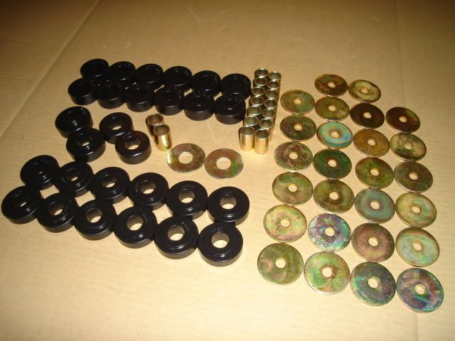 I jacked up the passenger side of the Tempest body first after removing all the bolts on that side and loosening all of the bolts on the other side. The front of the body still came up before the rear even with the jacking point this far back. 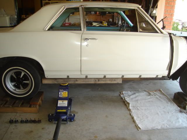 Old mount at the rear of the car. 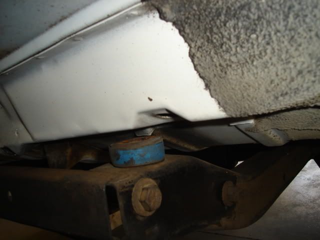 Two old mounts at the front below the firewall. The car doesn't need to come quite this far off the frame to remove them. 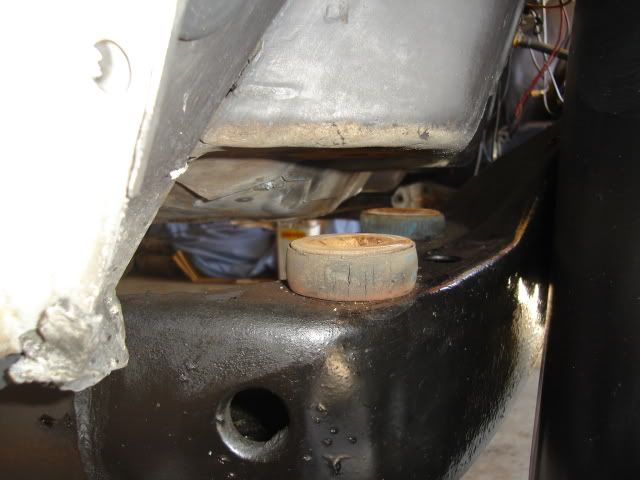 A look at the center frame mount area with the old mount removed, right next to the seat belt mounting point. 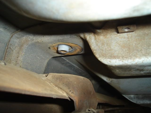 The bolt holding the front inner fender to the frame needs to come out on both sides (driver's side shown), this important step is not mentioned in the body mount installation instruction sheet. I took the brake hose bracket loose from the frame as well. 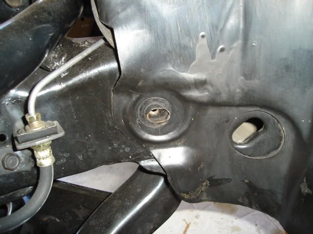 The steering column needs to be taken loose at the rag joint and loosened under the dash so you can pull it back about 1" or a little less. Another important thing that is not mentioned in the instructions. 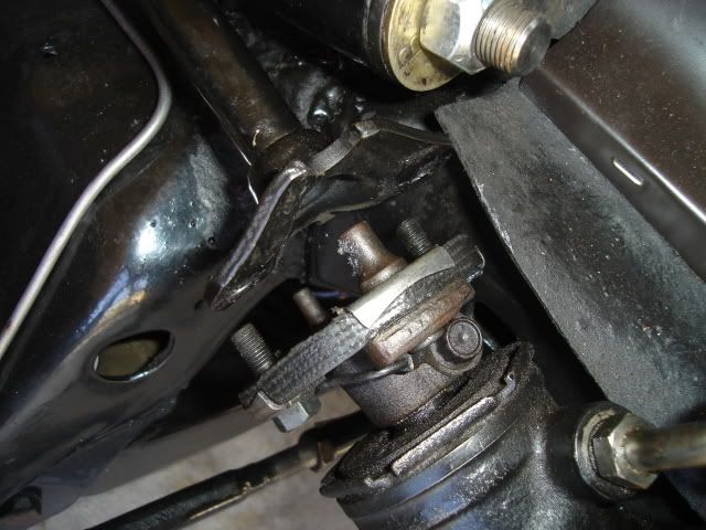 Old mounts removed, in pretty sorry shape. The rearmost ones (seen at the left) were compressed less than the ones closer to the center and front of the car. The original body bolts were in good shape and after some work with a wire brush they were reused after coating the threads with copper anti-seize compound. 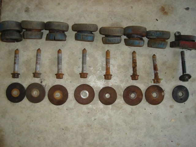 New reproduction 3/8" steel fuel line from Performance Years. They all come with a soft bend in the middle for shipment that's easily straightened out before installation. 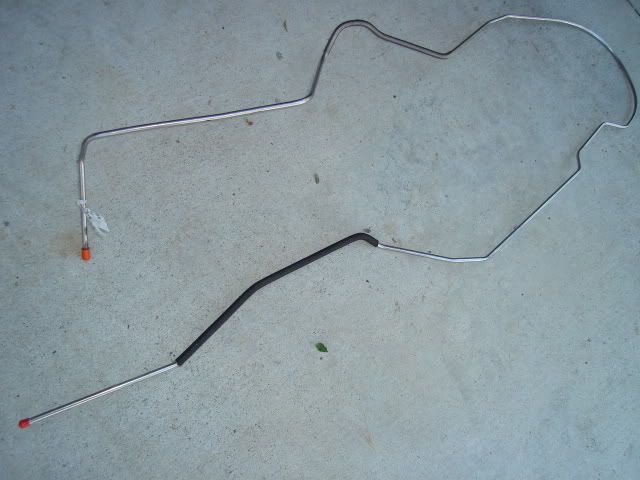 All straight and ready for installation. The 1964 -'67 A-body cars came with 5/16" line from the factory and that is the size you'll see in the PY catalog. Just ask them and they will do it in 3/8" for you by special order. 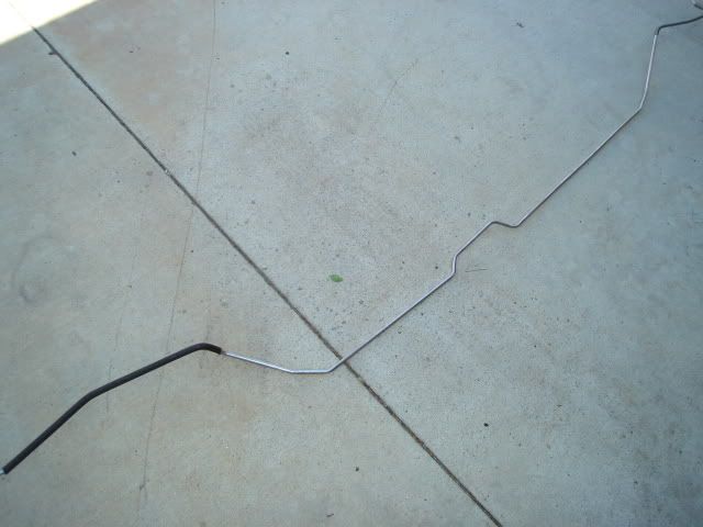 After finishing the passenger side mount installation and leaving the bolts loose I jacked up the driver's side. I jacked up the body a few more inches so I could snake the new fuel line into place. After looking things over I decided that feeding the line through the rear wheel well opening would work without having to bend up the line. 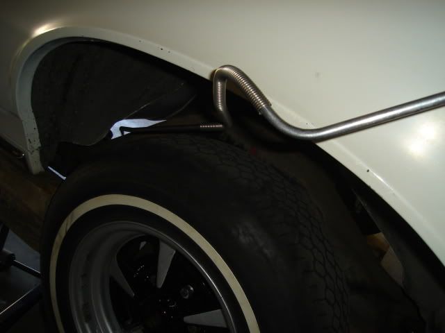 Feeding it in. 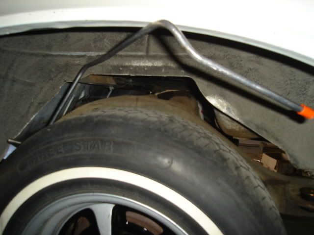 This shot gives you an idea of where it has to go near the rear. 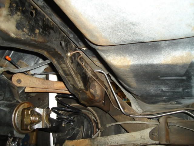 Here you can see it running towards the front of the car. The 3/8" line clips right into the three 5/16" factory clips on the frame making for a neat and easy installation. 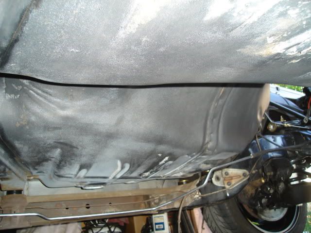 Rather than run the line through the front frame rail and out the front crossmember like the factory would have I bent the line so it would hug the firewall and head upward to meet up with the LS3 fuel rail on the driver's side. 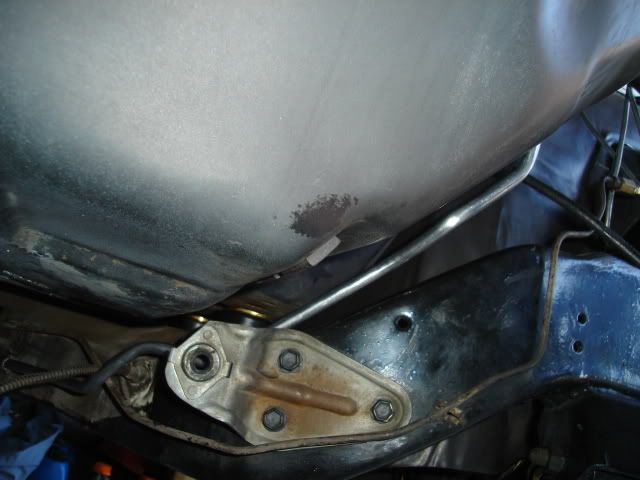 After I finished up the bending I slid the protective sleeving that was originally provided to keep the line from chafing inside the front frame rail over the bends. This will help to insulate the line and keep it from rubbing where it comes close to the frame and firewall. The fuel line is tucked in nice and tight so it will clear my column shift linkage. 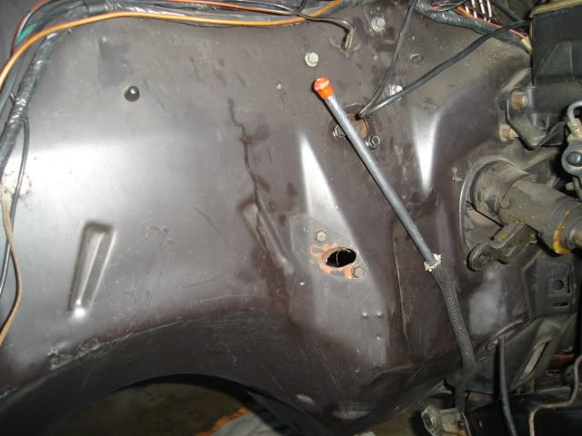 Here's why you need to take the steering column loose at the rag joint, the body needed to move upward pretty far to get the mounts and especially the fuel line in. 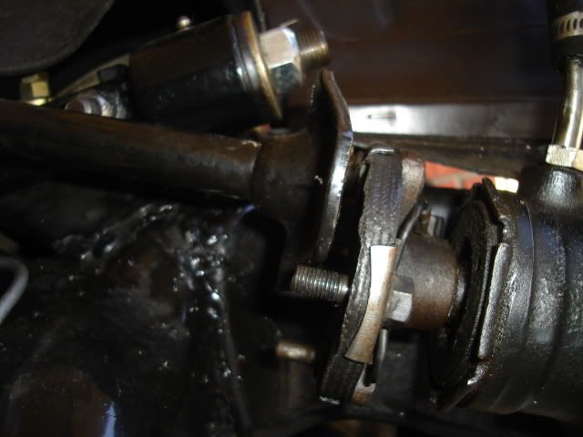 That's all for today, I took advantage of the perfect 75 degree weather and got a lot accomplished. Moving forward. |
|
#230
05-25-2009, 12:21 AM
|
||||
|
||||
|
Installed the A/C condensor.....
.....and drier today. Another nice 75-degree day that I couldn't afford to waste if I want to get this car together anytime soon.
The radiator core support needed two 1.25" holes drilled in it so the hoses can pass through it. Measurements for the hole locations are in the kit installation instructions. 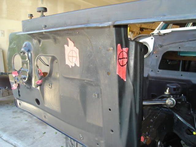 Since I don't have a 1.25" diameter chassis punch in my tool collection I drilled a series of smaller holes right next to one another. After knocking it out I finished it to size with a half-round file and painted the bare metal edges of the hole. Even if I had a large 1.25" drill bit using one would have torn up the sheetmetal when it broke through. 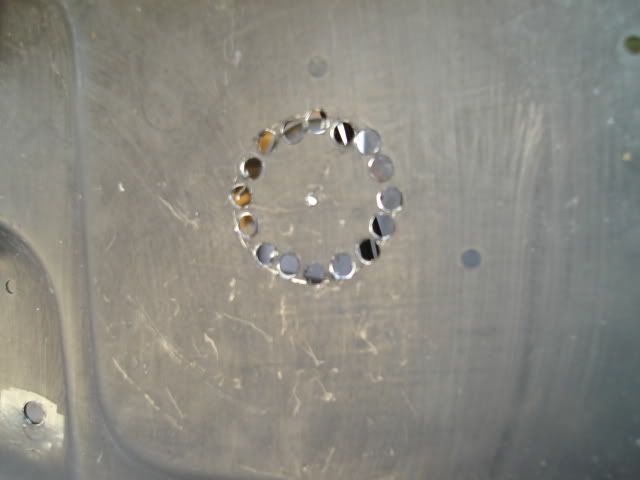 Both holes are now finished, the irregular stamping shape around the hole on the right would have made using a chassis punch impossible anyway. 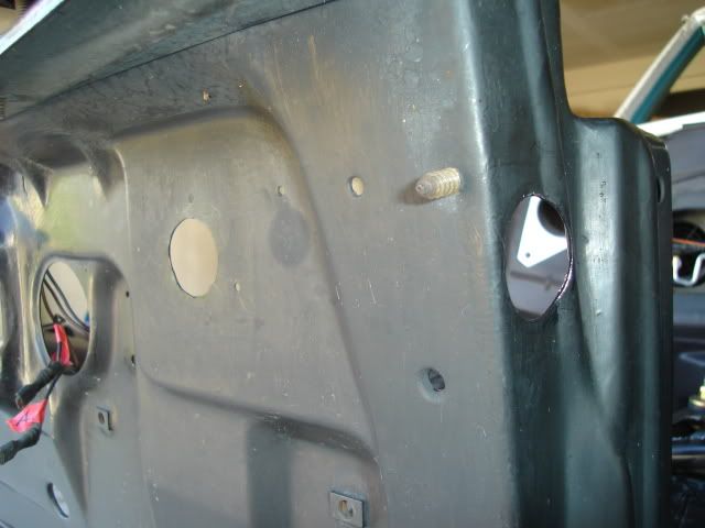 Drier mounted inside the core support, the 1.25" hole (1" rubber grommet now installed) lines up the inlet port on the drier. 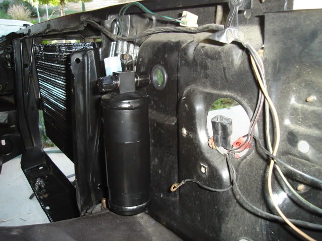 Condensor is now bolted in place, the 4 mounting brackets supplied in the kit lined up perfectly with the 4 existing holes in the core support. 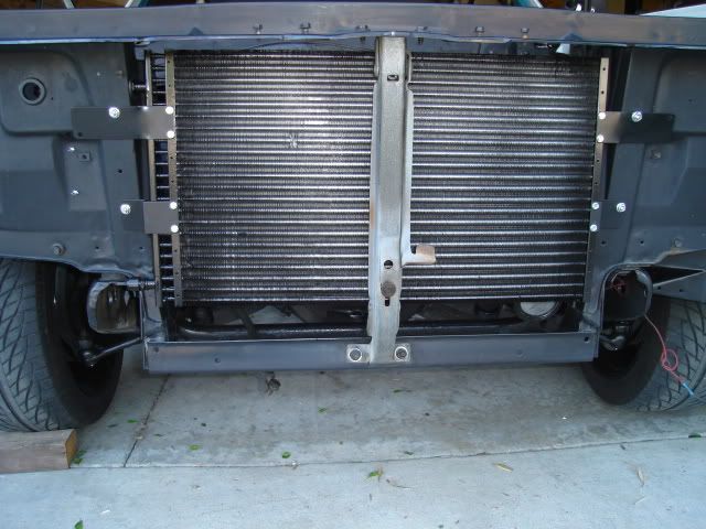 I did a test fit of the main A/C and heater unit under the dash. Two existing holes in the firewall serve to locate it and hold it in place along with two small brackets that bolt under the bottom edge of the dash. I needed to drill a 3/4" hole for the evaporator water drain tube and I wanted to make sure everything lined up before I drilled the hole. 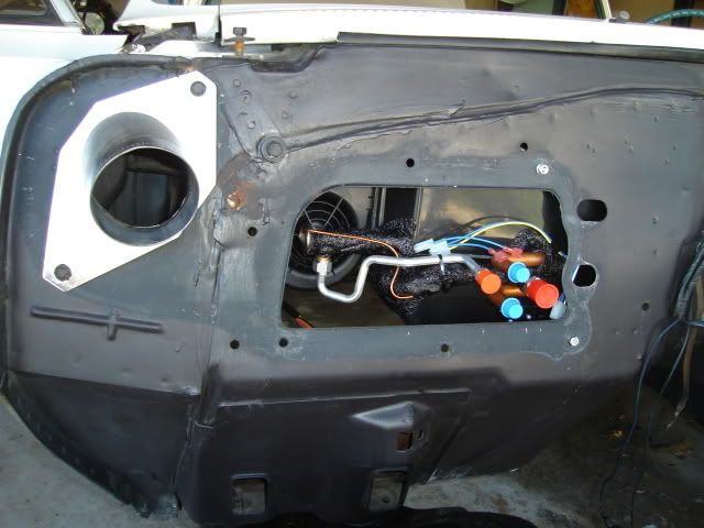 I climbed back inside and removed the old firewall pad and wiped down the inside of the dash and firewall. Also removed the e-brake mechanism and the water temp and oil pressure gauges that were hanging under the dash, everything is now out of the way so I can start putting some new firewall insulation down. Set my new reproduction Chevelle engine mount brackets on the front crossmember just long enough to find out that I'll need to set the engine and trans in place in order to locate them. None of the holes that mounted the old Pontiac mount brackets line up with the new mount brackets. Little by little it's all starting to come together.
|
|
#231
05-25-2009, 01:15 PM
|
||||
|
||||
|
Nice work Bart.
For the fuel line I would get a 37 degree flaring tool and use a tube and nut to mate the hard line with a short length of braided teflon line. Andrew |
|
#232
05-25-2009, 11:37 PM
|
||||
|
||||
|
Quote:
Today I installed the new Spectra Premium Industries fuel tank, it's ready to go for EFI setups with a built-in fuel pump and tank level sender already installed. The tank filler neck needed a little adjustment to the side, some careful bending put it where it belonged after the tank was in place (easier to do before installation, but harder to see just how much to bend it) 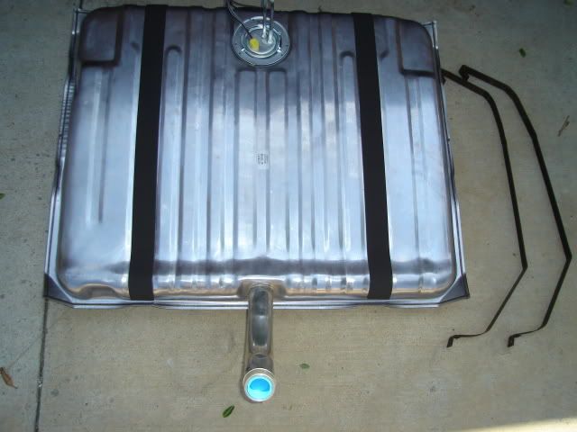 Pump and sender unit with the fuel feed and return lines and the pump and sender wiring. 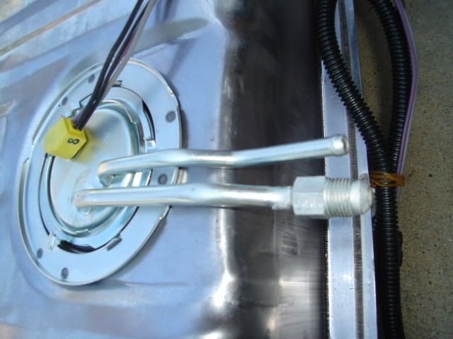 AC Delco GF822 fuel return regulator and filter unit for a late-model Corvette. 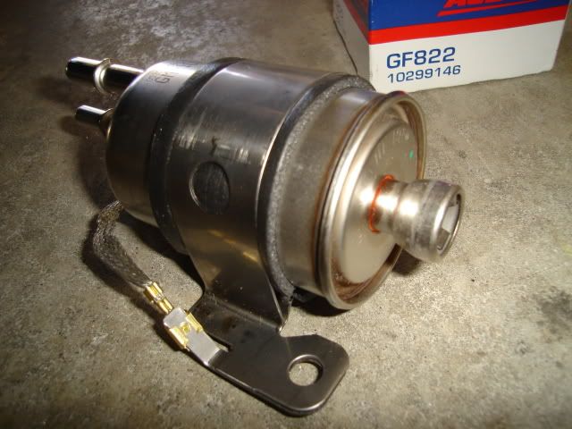 The regulator/filter will need to mount up here somewhere, as soon as I get a few of the pieces I need to connect everything up I'll find the right spot for it. 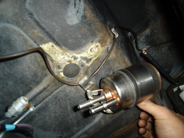 A look from the front side of the tank. 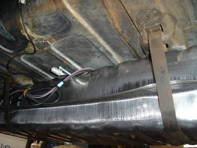 Tank install is complete, the only real hitch other than the filler neck being a bit off to the side was having to replace the two 3" long carriage bolts that tighten the tank straps at the rear. The straps wouldn't quite reach up far enough so I could put the bolts through the straps. I had to scrounge a couple of 4" long hex head bolts to use in the meantime, I'll go to the hardware store and get two 3/8-16 X 4" carriage bolts later to replace them. 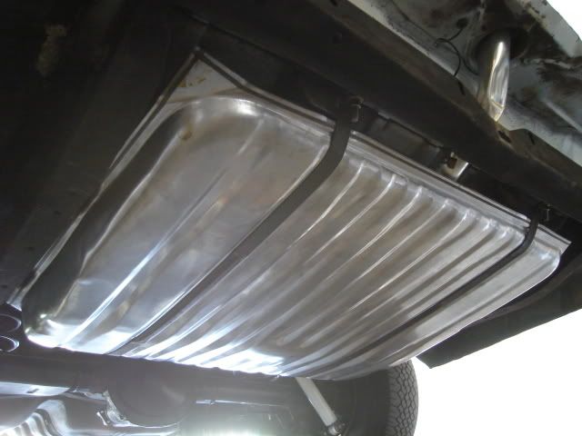 That's all for this 3-day weekend, The Tempest waits patiently until the next round of activity among the other cars and parts. 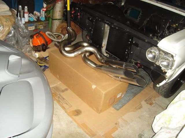
|
|
#233
05-31-2009, 02:27 AM
|
||||
|
||||
|
Mounted the fuel regulator/filter.....
.....and connected everything up with Gates fuel injection hose, pricey stuff at about $7 a foot but it should last pretty long before it needs replacing.
The filter uses quick disconnect push-in fittings common to late model cars and completely new to me. I bought a 12" long piece of 3/8" tubing with quick disconnect ends formed on both ends (about $10) and bent it so it would meet up with the 3/8" pre-formed reproduction chassis fuel line. I cut the quick disconnect feature off the end that connects to the chassis line and used a flaring to tool to form a bead on the end somewhat like the end on a factory line to retain the fuel hose better after it's clamped. The repro line only needed a 90 degree downward bend added as close to the end as possible. I didn't need cut the end off the line was able to keep the beaded end. At this point none of the hose clamps have been installed. 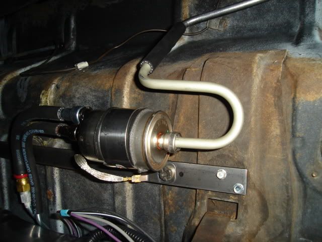 I bought 2 push-on quick disconnect fittings (about $8 each) to mate the 3/8" inlet and 5/16" return on the filter to the tank fuel pump lines. The tank lines come with fittings already made to accept rubber fuel injection hose, the new quick disconnect fittings went on the filter so that fuel injection hose would connect up to it. I hung the new 2-1/2" tailpipes temporarily to make sure I was keeping my lines as far away from the hot exhaust as possible. The filter mounts on a 22" long piece of 1" X 3/16" mild steel strap, it mounts to the structure underneath the trunk pan that supports the fuel tank. The filter mounting bracket was removed and painted black after these pics were taken. 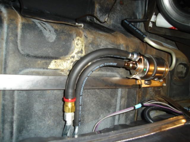 After doing some measuring on the engine I came up with the final configuration for the fuel line end on the engine side of the system. I took the line loose from the chassis clips and pulled it down far enough that I could use a tubing bender on it and put a 90 degree forward bend at the very end, again keeping the beaded end. It was bent a couple of inches toward the driver's side and then secured with an Adel clamp. Had to get this done before the engine goes in, no way to get the bender in after that is in there. 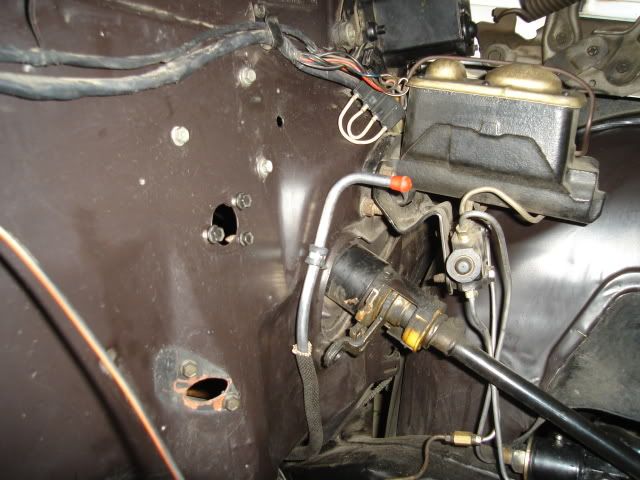 Still need to fab a couple of blockoff plates to close up the holes where the throttle cable and pedal pivot used to mount on the firewall as you can see in the above pic. Mounted the readjusted the rear bumper today as well, the body has dropped down by about 1/4" after installing the new poly body mounts. That's a good thing because it makes the car look a little lower and every little bit helps. |
|
#234
05-31-2009, 04:44 AM
|
||||
|
||||
|
Man, you do GOOD work Bart!
|
|
#235
06-01-2009, 12:29 AM
|
||||
|
||||
|
Quote:
Today's task was to mount the radiator and fans. Here's a look at the 24" wide Griffin universal aluminum radiator and OEM replacement late 4th-gen F-body twin fans and shroud assembly from Dorman. 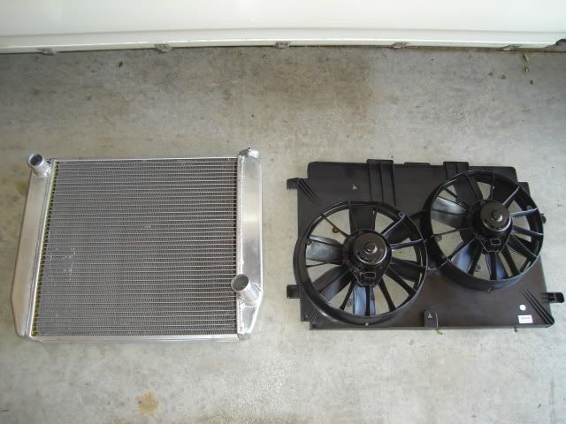 Fabricated some suitable mounts for the radiator using some old 3-row radiator mounting brackets left over from my '64 GTO. I did a little blacksmithing and reconfigured the shape of the saddle, the original unmodified one is on the right. I was able to reuse the lower rubber insulators that were already on the Tempest core support which is made for the 2" taller heavy-duty and A/C radiators. 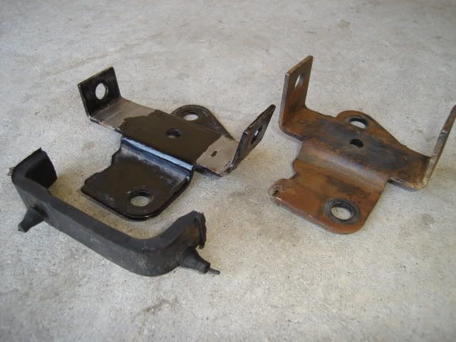 A look at the 4-row radiator mounts that are welded in place at the factory on A/C core supports, the bolt-in ones that I am using now are only used on the standard non-A/C radiator supports. 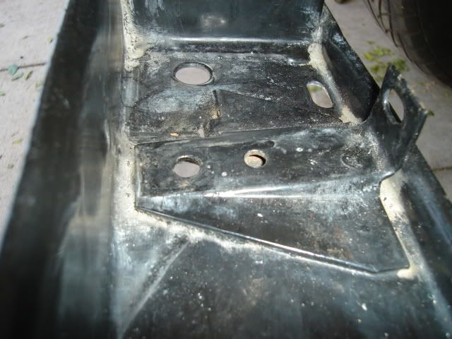 The newly reconfigured mount with the insulator installed being checked for fit. 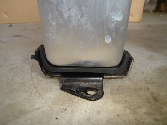 In order to put the radiator at the correct height in relationship to the core support opening I made some tubular standoffs from some thickwall 1/2" O.D. stainless tubing just a tad over 1" long. Now the radiator core is centered from top to bottom in the core support opening, the radiator core itself happens to be exactly the same size as the opening (purely luck). After carefully moving things around to find the ideal location I drilled the four 5/16" mounting holes. Passenger side looking from the engine side. This one is mounted directly over the old mount. 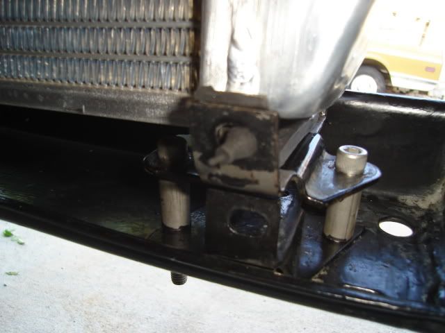 Driver's side looking from the front. This one was mounted 1" to the driver's side instead of directly over the old mount, this is just how everything happened to fit right. 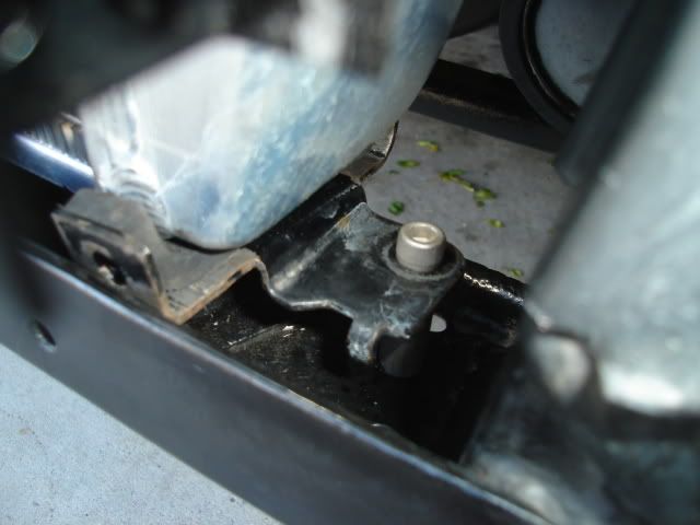 Radiator is now in it's proper place and held at the top for now with a piece of wire, I still have to fabricate the top center support bracket. 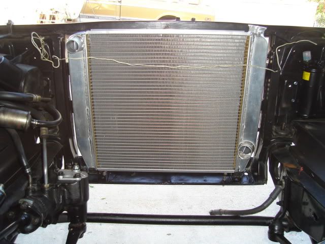 Fan package with radiator hose holes marked for cutting. The 18" height of the shroud exactly matched the height of the core, good luck is again with me. The 26" shroud width matches up exactly with the width of the opening in the core support too. 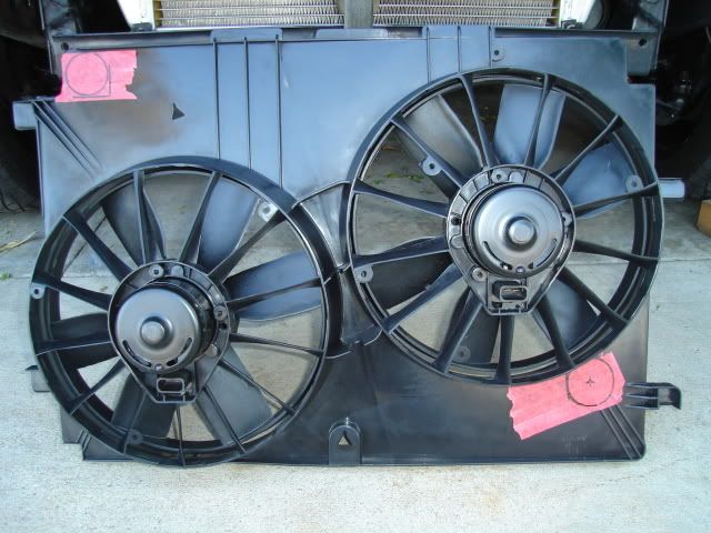 Holes have been cut and the unit is set in place to check fit. 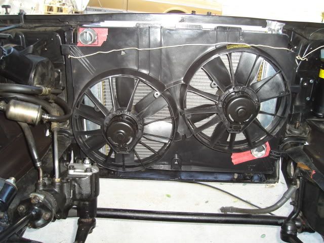 Looking from the passenger side you can see where I'll need to come up with some filler pieces to bridge the gap between the core support and the fan shroud. 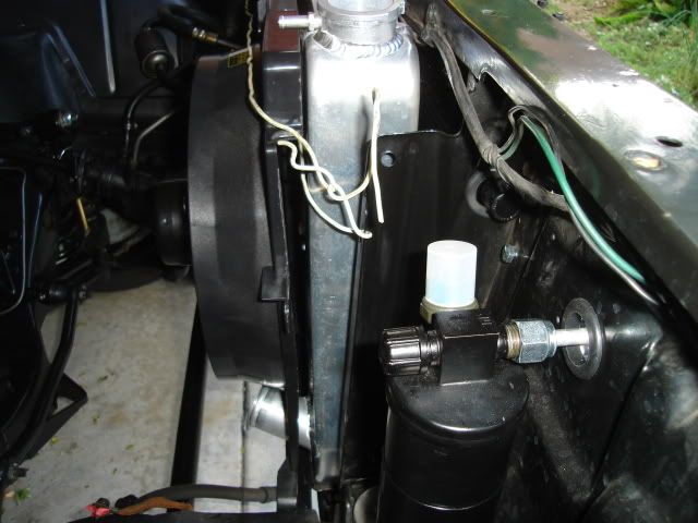 The shroud will need the 4 corners notched some to bring the shroud in a little tighter to the radiator, by almost 1/2". 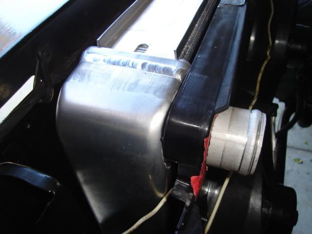 That's all for this weekend. Stayin' on it. |
|
#236
06-01-2009, 09:26 AM
|
||||
|
||||
|
Looking really good B-man!
__________________
North Dakotas fastest REAL GTO 10.10 @ 131 MPH in the 1/4 Hoping to get it back together some year. www.jandjrepairandrestoration |
|
#237
06-01-2009, 10:14 AM
|
||||
|
||||
|
LS3------> 64 Tempest
GO B-man go-Go-B-man GO-b-mAN

|
|
#238
06-04-2009, 12:20 AM
|
||||
|
||||
|
Quote:
Quote:
 When you're involved with a big project there will always be mistakes made that need to be corrected. It turns out the exhaust pipe going over the rear axle would have been much too close to my fuel line, when I mocked up the tailpipe location to see if the line would clear it I didn't have it up high enough. I messed around trying to reconfigure the chassis fuel line and just couldn't get it where I wanted it. I cut off about the last foot of line and got out my flaring tool so I could use an inverted flare union to join it up with a new piece of 3/8" steel line bent in the correct configuration. I put another inverted flare on the piece of line that goes into the filter and joined it up with the newly bent line using another union. 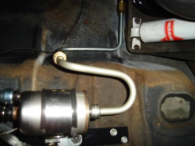 The end result is a lot cleaner-looking than before and eliminates a small piece of rubber fuel hose. Now the tailpipe doesn't even come close to the line, in the picture it has been dropped down so I could access the fuel line. 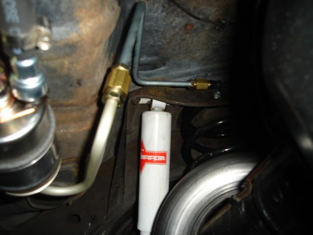
|
|
#239
06-04-2009, 05:46 AM
|
||||
|
||||
|
Geez, I just thought I was meticulous.
That is fine, Bman! |
|
#240
06-07-2009, 02:01 AM
|
||||
|
||||
|
Got down under the dash today.....
.....and started to mock up the A/C setup into place. I need to have all of the A/C and heat/defrost items that go under the dash in their correct locations so I can find a way to fit the Speartech controller and part of the harness in there. I'll need to find a good location on the firewall for the harness to pass through to the engine compartment.
I need to figure out where everything will go, get it all mounted and then remove all of it. After all of that is done I can finally start installing some high-quality firewall and floor insulation. I'll be using a layer of Damplifier Pro first and then a layer of Luxury Liner Pro on top of that on the inside of the firewall, from Second Skin Audio. The A/C unit is mounted in place against the firewall with both support brackets installed on the dash bottom edge. 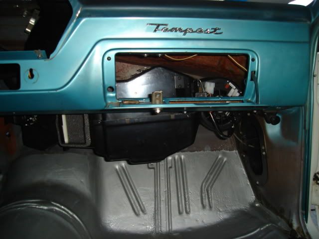 Heater and defrost ducting in place. The original defrost ducting was cut off on the bottom and a defrost hose adapter added from the kit. 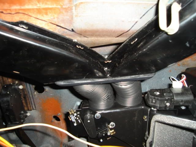 Here's the 'stubby' glovebox insert that's supplied in the kit. 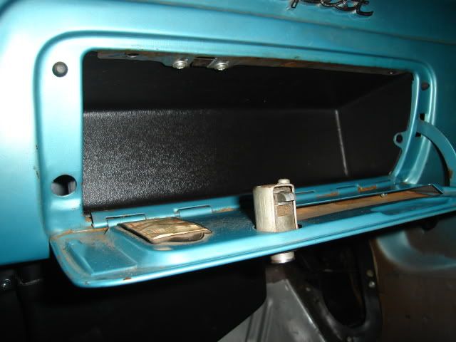 After putting most of the A/C stuff in place I started on the controller and harness. First thing to do will be mounting the drive-by-wire accellerator pedal. Here are some shots of the accellerator pedal mounted to a bracket I made up out of 2" X 3/16" angle iron that's 7-1/2" long, it's plenty stout and won't flex. I drilled tapped the bracket with 5/16-18 coarse thread for the two bolts that mount it to the firewall and 1/4-28 fine thread 2 places to mount the pedal assembly to the bracket. 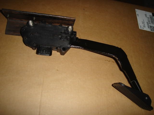 Later on the bracket will get cleaned up some by removing some unnecessary metal in a few places and rounding off the corners, a little black paint will finish it off. 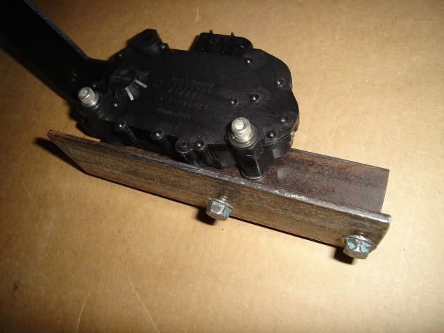 The pedal bracket mounts at the very top inside the firewall using two existing bolt holes (opened up to 5/16") that were originally used to mount the voltage regulator. 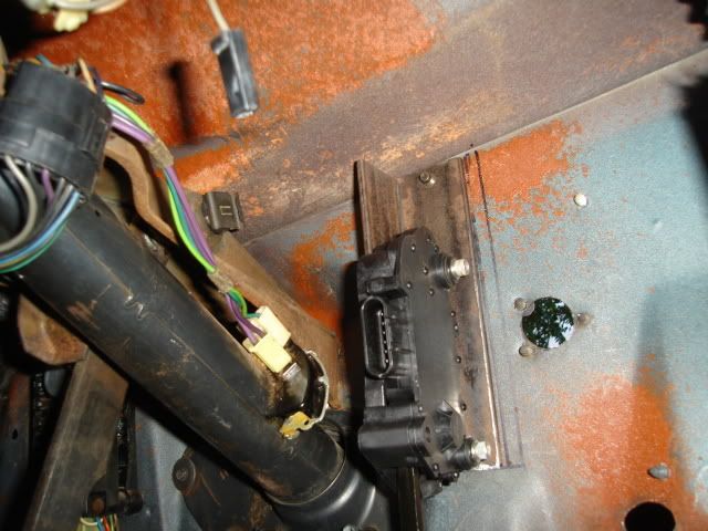 Firewall side showing the two bolts I used to attach the bracket. They're actually stock Pontiac V8 valve cover bolts with flanged heads. Keep Your GM Car All GM. There is also a third smaller existing hole you can see at the bottom that was originally used for a small sheetmetal screw. For a little more rigidity I'll put a 10-32 thread hex head bolt there after drilling and tapping the bottom corner of the pedal bracket. 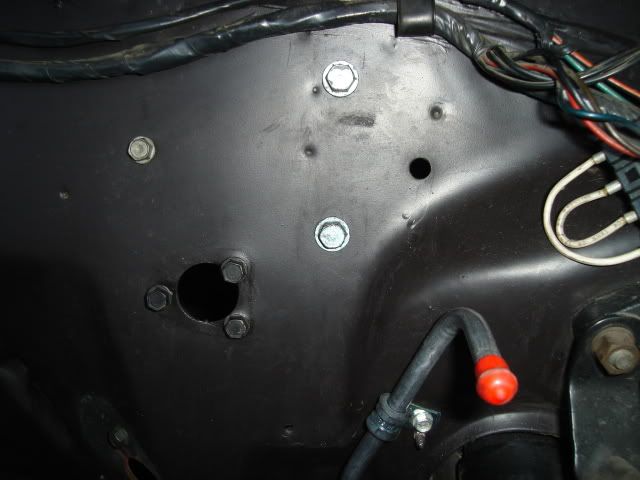 Pedal mounting position is very close to where the original one went. 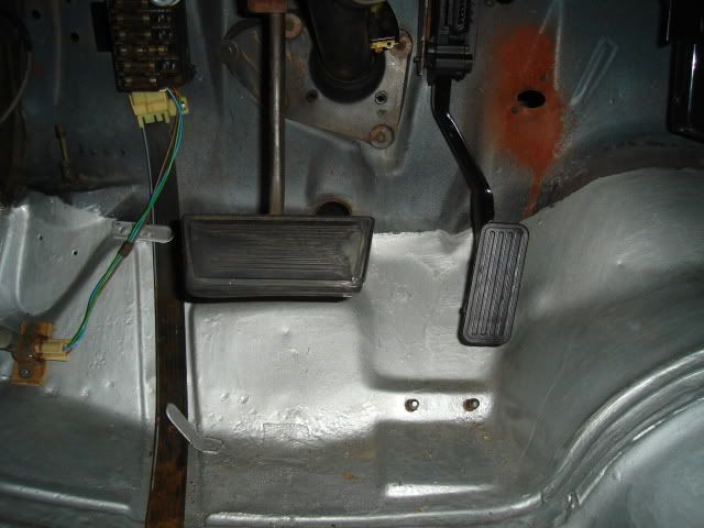 Here you can see how the original pedal sits directly over the new pedal, positioning is right on the money. Later on I may decide to use the original pedal to actuate the throttle, making that work won't be too difficult. 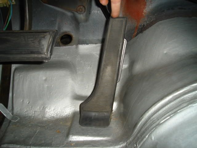
|
| Reply |
|
|
The PY Online Forums is the largest online gathering of Pontiac enthusiasts anywhere in the world. Founded in 1991, it was also the first online forum for people to gather and talk about their Pontiacs. Since then, it has become the mecca of Pontiac technical data and knowledge that no other place can surpass.






 Linear Mode

