


| FAQ |
| Members List |
| Social Groups |
| Calendar |
| Search |
| Today's Posts |
|
#321
 08-24-2009, 10:54 AM
|
||||
|
||||
|
Bart-
On the trans cooler, if you find that the smaller cooler is not sufficient, can you run two of the smaller coolers behind front bumper? one on left side, one on right side? Scott. |
|
#322
08-24-2009, 01:30 PM
|
||||
|
||||
|
b-man have you looked at this fan controler?
http://www.dccontrol.com/introf0.htm
__________________
Its ok to giggle and snicker, Dont laugh and point |
|
#323
08-24-2009, 07:13 PM
|
||||
|
||||
|
Frederic,
Thanks again for the very helpful info, I'm a novice when it comes to automotive electrical systems. Your input on my build has truly been instrumental in leading me in the right direction on many different details.  I'm considering using my stock AM radio to play an Ipod using a RediRad (PY p/n RPZ189):http://forums.maxperformanceinc.com/...d.php?t=577798 I don't need nor do I want a killer stereo in my Tempest. A couple of 6X9s in the package tray and an updated speaker assembly in the center dash speaker location would be plenty for me, as long as it has some reasonable clarity and volume I'll be happy. ponjohn & Ollie, The Speartech ECM will control the EFI and fans so I have that much covered, now it's a matter of getting the correct relays, circuit breakers and the proper wiring to make the fans and everything else work reliably. Scott, My first thought was running two coolers, but the added plumbing and blocking more of the radiator and condensor airflow kind of discourages me. I'm still thinking about running two of them though so that when I'm running the car hard my very expensive tranmission won't suffer. |
|
#324
08-24-2009, 10:33 PM
|
|||
|
|||
|
Bart
If you want to talk in more detail about the electrical part, PM me and we can swap phone numbers. My degree is in Electrical Engineering and computer programming. I am well qualified if you want assistance. Frederic
__________________
68 Lemans - GTO appearance LS3 68 Eldorado - waiting for restoration 96 Roadmaster Wagon 2014 Infiniti Q50S Hybrid Marietta GA |
|
#325
08-25-2009, 10:36 PM
|
||||
|
||||
|
Quote:
I'd like to take you up on that, I hope you don't mind me asking some pretty basic questions. Over and over again.  ------------------------------------------------------ Okay, back to the Tempest at hand. I decided to buy two B&M transmission coolers. No way I'm taking any chances with my nice transmission. The coolers will be arriving in a couple of days along with some 3" stainless steel V-band connections that will be welded to the exhaust system just before the mufflers. In order to get the transmission out for service I have to be able to easily drop the X-pipe out of the car, so the V-bands will solve that issue. This car must be as to easy to service as I can make it. Also ordered up a Wilwood proportioning valve to adjust front to rear brake bias. I will buy a new master cylinder locally, the one I need is a 15/16" bore unit for a '77 Monte Carlo with manual front discs. Thanks again to all here who have offered ideas and assistance with this project.   
|
|
#326
09-07-2009, 12:46 AM
|
||||
|
||||
|
.....for my twin trans coolers.
They tuck right behind the bumper way down low, the top half of the coolers will be exposed to fresh air coming in from the slot in the bumper. After removing the front bumper this is what I have to work with. 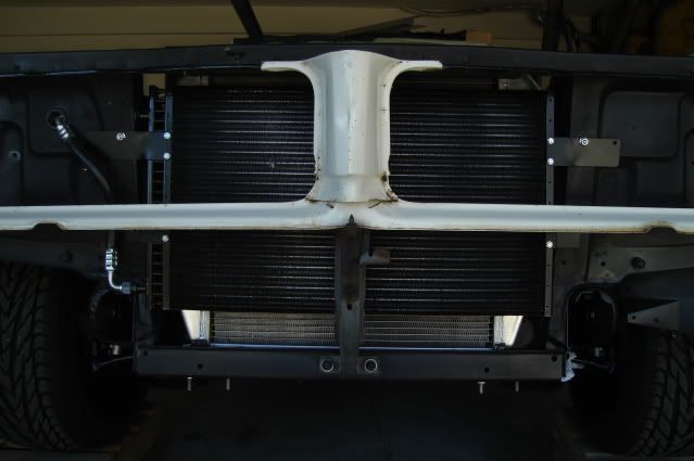 Both coolers are mounted to a piece of 1" wide X 3/16" thick X 29" long mild steel bar. The bar mounts to a pair 1-3/4" long standoffs (spacers), the bar is about 3/8" from the front of the condensor fins. I was able to use two existing 1/4" holes in the core support to mount it, worked out just perfect! Down below I still need to fab up a pair of lower support brackets from the same mild steel bar, they will bolt to the two lower 3/8" studs that mount the hood latch support in the center and two exisiting 3/8" holes at the bottom corners of the core support channel. 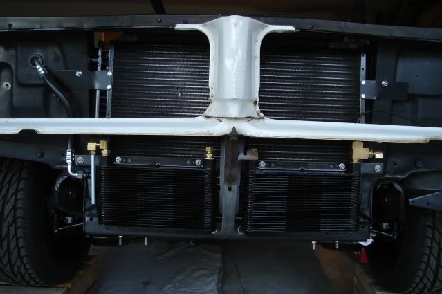 I used a large 1/2 NPT run tee at the top outlet of the second cooler so I could install a trans temp sender for the Autometer trans temp gauge. This should give me a pretty good temperature reading of the cooled fluid before it heads back to the transmission. 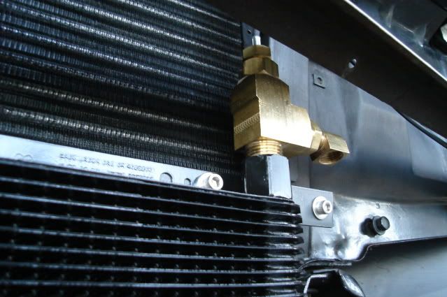 A shot of the 3/8" tube loop that connects the outlet of the first cooler to the inlet of the second cooler. There's plenty of clearance between the tubing loop and the hood latch lever so I won't burn my fingers on the hot tubing. All of the tube fittings are brass inverted flare, already proven to be reliable by the OEMs. 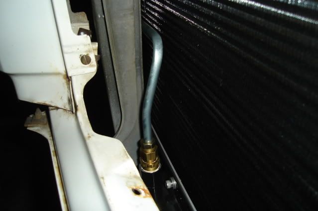 None of the brass fittings or the tube loop can be seen with the bumper and grilles in place, the rest of the cooler plumbing will be hidden behind the bumper as well. Tomorrow I hope to finish up the plumbing on both coolers and the lower mounting brackets. Thanks for looking. 
|
|
#327
09-07-2009, 01:45 AM
|
||||
|
||||
|
Clever and sanitary oil cooler install, Bart. Nicely done
 . .Les
__________________
Les Iden ---------------------------- '65 Buick Sport Wagon Custom, 340, T350, 3:23 '66 GTO Post/468, 700R4, 3.31 (Mike's as of 9-16) '68 Grand Prix/455, dual AFBs, T400, 2:93 posi (sold) '72 TA tribute/461, T400, 3.08, (Russ's as of 9-16) '97 Mitsubishi Eclipse Spyder Turbo, Konis, 5 speed '09 Torrent GXP, nav, Sun & Sound pkg., Bilsteins |
|
#328
09-07-2009, 02:01 AM
|
||||
|
||||
|
Quote:
The two factory horns that bolt to the inside of the front bumper brackets on these cars are less than 1/2" away from the outside corners or the coolers. Where there's will there's a way. I can't have my transmission overheating when I'm thrashin' on this thing through the canyons, I'm thinking it won't now.....
|
|
#329
09-07-2009, 11:14 PM
|
||||
|
||||
|
.....on the twin-trans cooler installation today.
I put the front bumper back on and adjusted it as closely as I could to where it will be on the finished car. After checking the clearance between the coolers and the bumper I found they needed to be shifted upward by one inch. This puts the top of the cooler fins right at the top of bumper slot, a little bit more ideal for catching cooling air and adding some much needed clearance at the bottom of the coolers to the bumper. I put the driver's side grille in to check for clearance too. The brass fittings and tubing are hidden from view in the grille area. 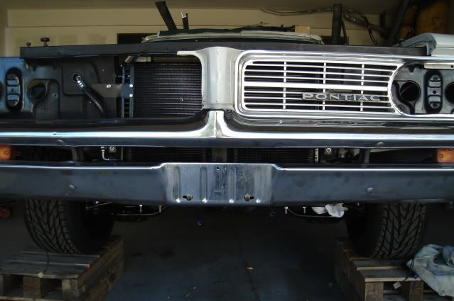 With the bumper removed again and the various component clearances confirmed it was time to bend up some 3/8" steel hard lines. 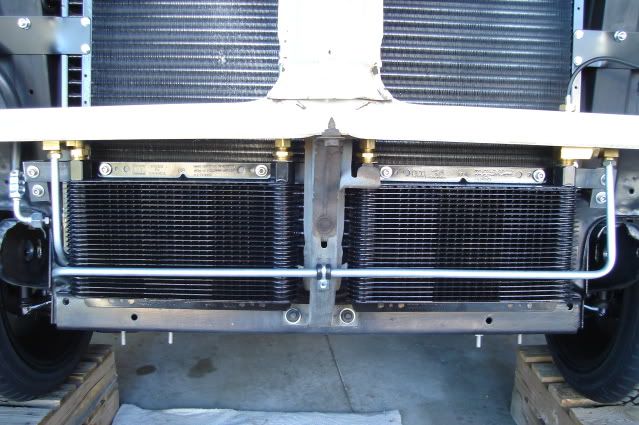 There was a small 'window' of space for both of the cooler lines to pass through the core support at the bottom corner. 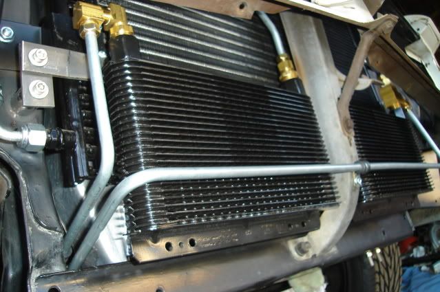 Both lines terminate a few inches past the core support, the 3/8" inverted flare unions were staggered to make it a little easier to swing a line wrench on them. I bent the lines so as to leave access to the hole in the frame for the front bumper bolt. 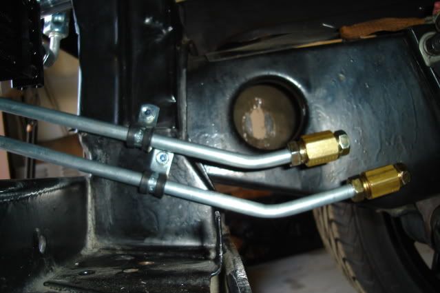 I still need to make up the bottom support brackets, but I did manage to get all of the plumbing finished on the front end. Hope everyone had a great Labor Day weekend!
|
|
#330
09-13-2009, 11:25 PM
|
||||
|
||||
|
.....so I can make up more of the cooling lines.
There will be zero access to the cooling line fittings on the side of the trans with it installed, so I need to make up some short lines that will be considered part of the complete transmission assembly before it gets installed for the final time. Here's what I have to work with. The 90-degree inverted flare fittings are the key to making this work. The fittings have 1/4 NPT threads but the trans is made for a straight thread fitting. The thread diameter and pitch is the same for both, but the pipe thread is tapered to make it seal. Before installing the fittings I used a 1/4 pipe tap to try to taper the last couple of threads in an attempt to help out with the sealing for whatever it's worth. I used a little teflon paste on the threads and got 'em good and tight. 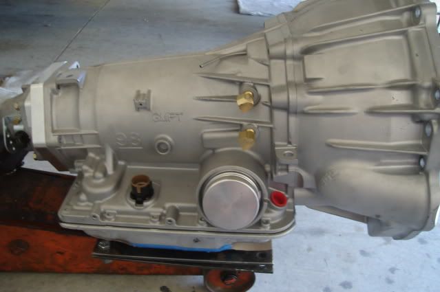 A shot of the finished 3/8" steel lines before installation. 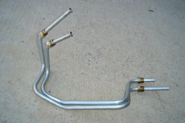 Lines are now installed. I had to run them towards the rear then down and forward because there's no room to run them forward right off the fittings, the trans dipstick tube will be in the way. 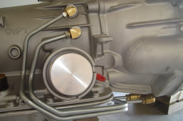 The trans wiring needs to travel right next to the lines and right around the circular servo casting projection before it plugs into the large connector (just to the left of the lines in the above pic), everything is a tight fit in the trans tunnel. Rather than bash the trans tunnel out another inch or two for clearance, I packaged it all tightly to keep the tunnel as small as possible so my stock rubber interior flooring will still work. 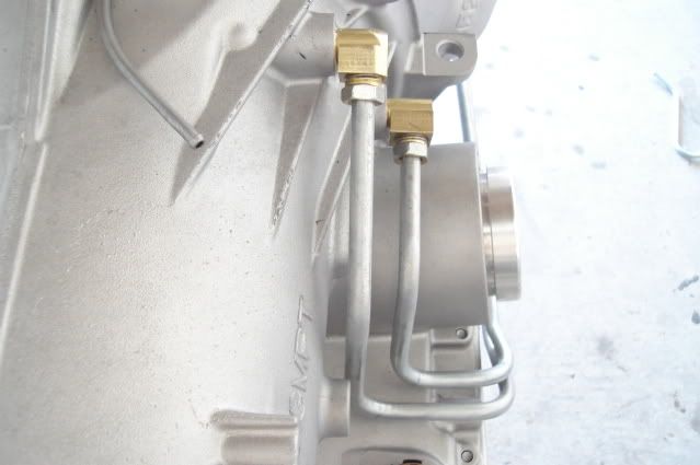 Shot from the bottom where the lines terminate underneath the bellhousing. After the trans goes back in and the headers and starter motor are installed on the engine I can make up the 2 lines that will connect the front twin cooler lines to these short trans lines. 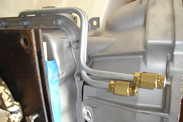 The weather was beautiful today in the mid to low 80s, so I took advantage of that. Gotta keep moving on this.
|
|
#331
09-15-2009, 11:12 PM
|
||||
|
||||
|
Wow!! Nice work on those lines!!
__________________
1965 GTO, 408 tri-power, 4 speed, Currie 12 bolt w/3:42's, Hurst wheels |
|
#332
10-06-2009, 10:52 PM
|
|||
|
|||
|
I'm amazed at this engine. I weighed the composite LS3 intake completely dressed with injectors, silencer cover, throttle body and fuel tube. 17-18 lbs... that's the same as a bare aluminum edelbrock manifold.
Nice work here! Thanks for the eyecandy. I will drop mine in this weekend if the rain doesn't come. Took the RX7 to the scale today to get the pre-swap 'stock' weight. 2860 lbs. Wonder if I'll lose or gain replacing the rotary. |
|
#333
10-06-2009, 11:16 PM
|
||||
|
||||
|
Thanks again everyone for the kind words.
Regarding the RX7 swap, my guess is you'll be adding about 100 pounds to the car. I doubt the Mazda rotary weighs in at 400+ pounds. The LS3 is a pretty amazing piece. Recently I was reading this LS3 street cam swap article: http://www.gmhightechperformance.com...son/index.html Tested with a set of Hooker Competition Ceramic 1.75-inch headers (PN 2469-1HKR) and an electric water pump the stock LS3 baselined at 471.3 lb-ft and 483.1 hp.  Not too bad for a 376-cube engine with a 204/211 @ .050 cam, lift numbers are pretty decent at .551"/.521". I'm thinking that expecting a 'real-world' 450 to 460 HP at the flywheel out of mine wouldn't be out of the question.
|
|
#334
10-11-2009, 12:49 AM
|
||||
|
||||
|
.....for a while today and made some decent progress.
I removed the old master, it's a 1-1/16" bore 2nd-gen F-body disc/drum manual brake unit that worked very well with the single-piston B-body calipers. I'm replacing it with a 15/16" bore 1977 Monte Carlo or Malibu disc/drum manual master that comes complete with the pushrod, a $35 item with an $11 core charge (pictured below in the foreground). That's right, no power brakes. Of interest is the two masters are configured backward from one another. The F-body master has the front brake reservoir in front, the Monte master has the front brake reservoir located in the rear. This means I will have to remake the lines from the master to the combination valve. 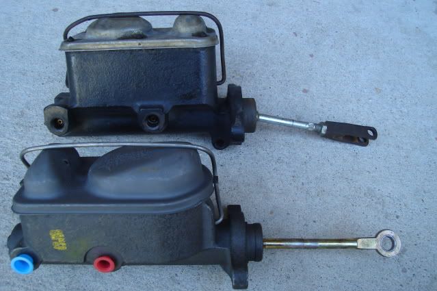 I was able to use the old 1964 Tempest single-master pushrod with the F-body master. For reference I measured from the mounting surface of the master to the center of the pushrod pivot pin, it looks to be right about 6". 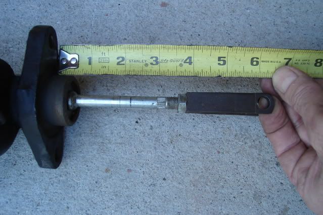 The new Monte Carlo master pushrod won't be quite long enough nor will it fit up to my brake pedal. It fits deep into the piston, by about an inch unlike the F-body master. 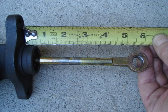 I will cut the new pushrod off at the cut line shown and thread it with a 3/8-24 die so it will screw in to the original Tempest brake pushrod clevis. It's just long enough to work. 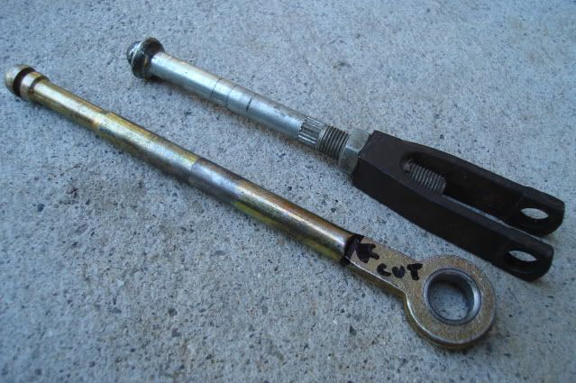 I will reuse the 2nd-gen F-body combination block and mounting bracket, the bracket has been slightly modified by bending the mounting tabs to tuck the combo valve up close to the master cylinder. The combo valve has been modified by removing the cartridge and spring (shown next to the end cap), they can be accessed after removing the end cap. The Wilwood adjustable proportioning valve ($42) will connect to the 3/16" brake line adapter fitting in the end cap, it's mounted on a simple angle bracket. I will adjust the front to rear brake bias using the Wilwood prop valve to prevent the rear brakes from locking before the fronts, especially under wet road conditions. 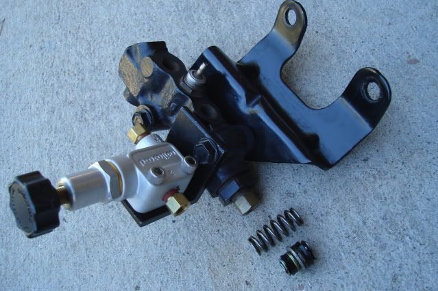 I made up some new lines from the master to the combo valve, plus a short loop to connect the adjusable prop valve to the combo valve. I was able to reuse and reconfigure the original factory 3/16" line from the front brake reservoir to the combo valve, but had to make up a new 1/4" line from the rear brake reservoir to the combo valve. All these lines were bent by hand, the tubing is pretty soft so it's not too hard on your thumbs. There's no way to use a tubing bender on these with the bends so close to the tube nuts. 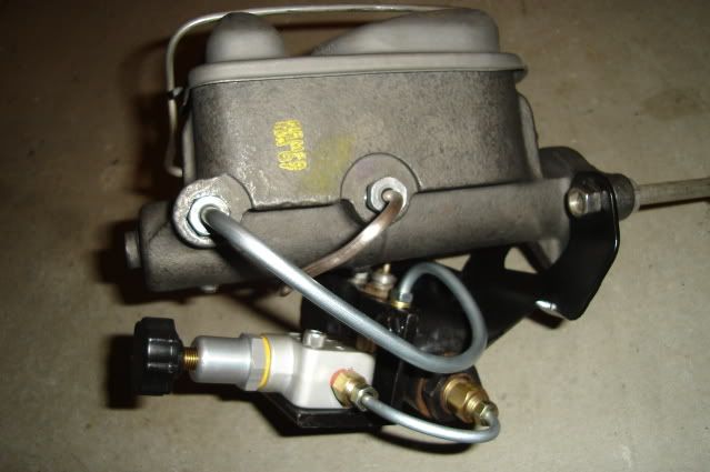 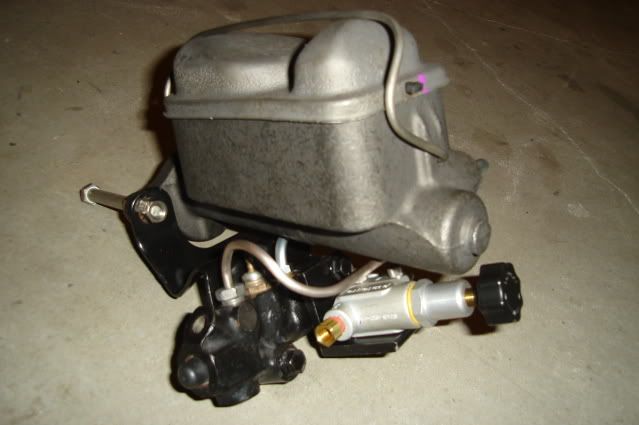 The completed assembly test fitted in place, the short loop from the combo to the prop valve clears the inner fender by about 1/2". 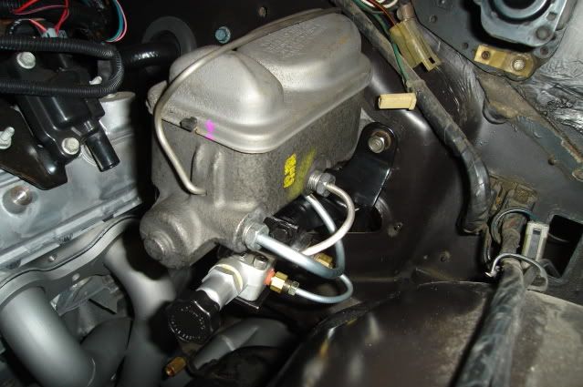 That's all for today.
|
|
#335
10-11-2009, 08:36 PM
|
||||
|
||||
|
How is the braking effort without a booster? I imagine it's a matter of getting the master and wheel cylinders sized properly.
|
|
#336
10-11-2009, 09:27 PM
|
||||
|
||||
|
Quote:
Pedal effort with the old 1-1/16" bore master and 12" B-body front discs really wasn't too bad, you had good control of brake modulation and it didn't take a ridiculous amount of effort to stop the car. When you pressed hard on the pedal you definitely had good braking power in proportion to that effort. They didn't fade easily and would lock up when you expected them to. ---------------------------------------------------- Today I finished making up all of the hard lines for the brakes. Again all of the bends were made by hand, making for some pretty sore thumbs by the end of the day. 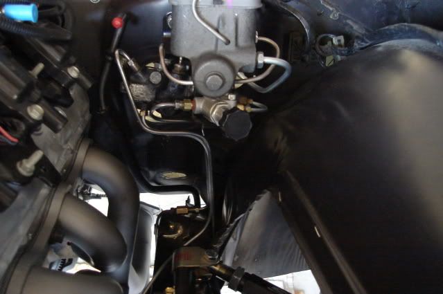 The lines coming down from the combo and prop valves were bent this way to leave room to pull the steering column in and out of the car. The line in front leads to the left front brake, the next one (60" long) goes under the engine along the front crossmember to the right front brake and the rear line coming off the prop valve connects up to the original rear brake line. 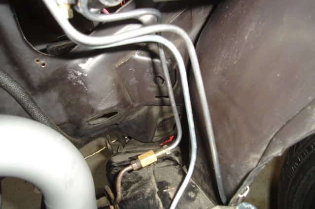 The 60" long line running under the engine terminates here, getting this line bent and routed was made a little easier with the inner fender out of the way. The engine will come out once more later on, I will tidy up the bends a little and fasten it down better at that time. 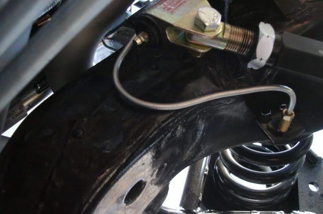 Another job out of the way that will bring me a bit closer to driving this old heap. Keepin' on it.
|
|
#337
10-12-2009, 10:42 AM
|
||||
|
||||
|
Bart-
looking good. imo, put on whatever headers you think you'll have the most fun driving. that starter R&R looks like a long list, but maybe only a couple hours? also, i agree with Jeff about heat shield for starter, and also consider heat shield for trans lines next to headers, back by collector. nice line bending. with the long lines you have now, depending on how you fasten them down, i'd think you'll be fine without a flex tube section? couldn't the line be run inboard, next to oil pan? thx for taking pics and keeping us updated! |
|
#338
10-12-2009, 06:56 PM
|
||||
|
||||
|
Quote:
Making up some kind of heat shield for the starter is a must and is on my long list of things to do. I may even swap out this starter for a smaller one that's used on the 5.3 liter truck engines, but I'll only do that if it solves the installation issue. My AC Delco reman starter cost $300, so right now I'm hesitating to do anything but try to make use of it. The lines will be supported right at the trans pan and in a couple of places on the inner fender, that should be plenty. The factory lines used on these cars are only supported in one place on the front crossmember, right next to a hot exhaust manifold. I wanted to run them right past the starter and next to the oil pan rail, but there's absolutely zero room. In order to make them up that way I'd have to run them under the oil pan in one area coming from the trans, that's not an option of course. |
|
#339
10-19-2009, 07:21 AM
|
||||
|
||||
|
Bart, I know the starter is back a few days but have you thought about taking it apart to install/remove? I had to do this with my round port motor, 4 speed TA with a scattershield. Pain in the butt but better than the alternative.
__________________
_____________________________ She woke up sunny side down and I was still thinking I was too proud to flip her over |
|
#340
10-19-2009, 12:47 PM
|
||||
|
||||
|
Quote:
At this point I feel lucky that there's just enough room to get the starter wires on. |
| Reply |
|
|
The PY Online Forums is the largest online gathering of Pontiac enthusiasts anywhere in the world. Founded in 1991, it was also the first online forum for people to gather and talk about their Pontiacs. Since then, it has become the mecca of Pontiac technical data and knowledge that no other place can surpass.


 Linear Mode

