


| FAQ |
| Members List |
| Social Groups |
| Calendar |
| Search |
| Today's Posts |
|
#1
 09-11-2009, 12:53 AM
|
||||
|
||||
|
A lot of us dream of building up one of these old warriors to drive on the streets and highways with a lot of horsepower. Unfortunately these beautifully-styled old Pontiacs came equipped with woefully inadequate brakes and handling characteristics for any real high-performance driving.
When you up the power to 400 or 500 horsepower or even more you really need much better handling and stopping ability. An expensive set of disc brakes looks pretty cheap in comparison to the body shop bill if you can't haul it down from speed. First order of business is gathering up all the parts needed. SPC front suspension arms. The lower tubular control arms will drop the car by one inch. The lower ball joint mounting position has been moved forward by about one inch, when you dial in additional caster for high-speed stability the wheel won't end up sitting toward the back of the wheel opening when looking from the side. The upper control arms are fully adjustable so no alignment shims are needed. This Pro-Lite set features lightweight billet aluminum hex adjusters and cross shafts. 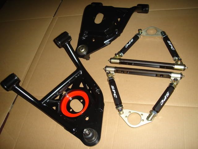 Currie Currectrac rear control arms. The uppers are fully adjustable so you can set the pinion angle, the lowers are lightweight billet aluminum. 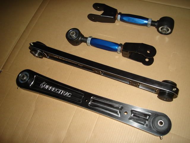 Forged aluminum AFX spindles (made for A, F and X-body cars) and billet aluminum A-body steering arms from ATS (American Touring Specialties http://www.t56kit.com/). They are designed to accept 1997 and up C5 & C6 Corvette hubs. 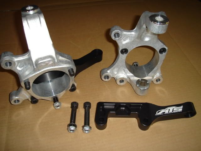 A set of C6 Corvette SKF racing hubs. I can't run the forged aluminum ATS spindles without these, I went for these heavy-duty parts instead of standard OEM replacement hubs hoping that they'll last me a lifetime. They can withstand the stress of hard cornering much better than the OEM hubs. Along with the front hubs I bought some new MOOG A-body upper ball joints and outer tie rod ends to complete the front suspension upgrade. 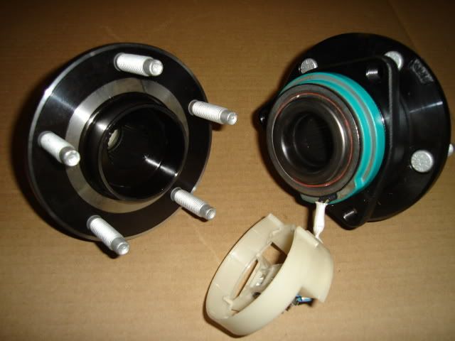 I went with C6 Corvette Z06 brakes. I decided to upgrade my brake package with some DBA (Disc Brakes Australia) 4000 slotted rotors and Hawk ceramic brake pads. Front rotors measure 355mm X 32mm (14.0" X 1.25") and the rears are 340mm X 26mm (13.4" X 1.00"). I'll have plenty of braking power to stop this train once it gets a-rollin', a set of 18" wheels will be required due to the size of these brakes. 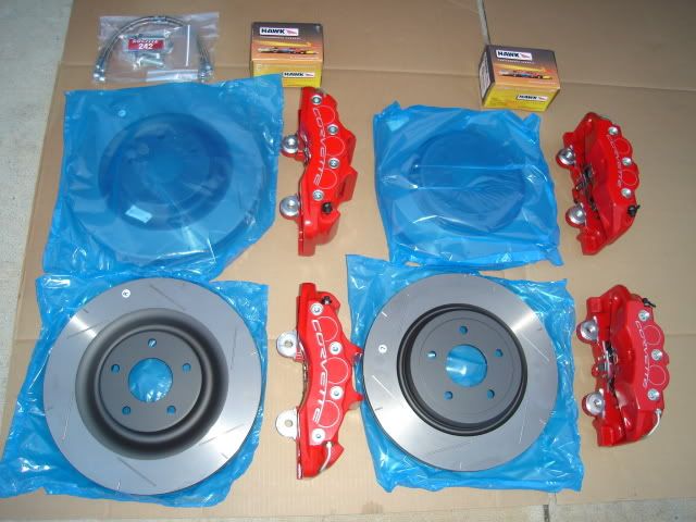 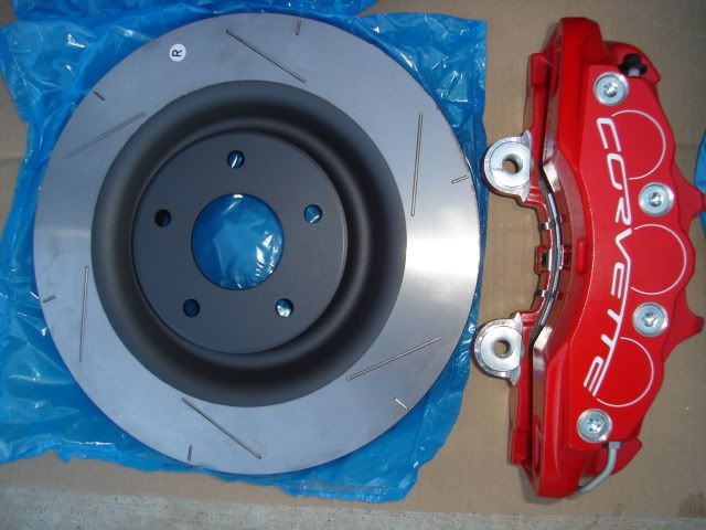 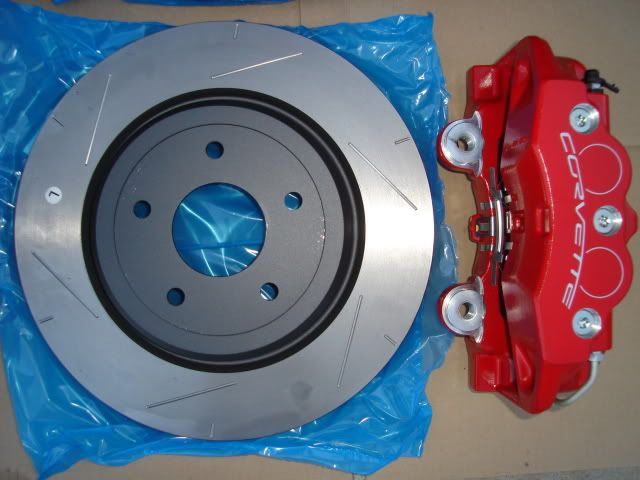 Some new Bilstein Heavy-Duty gas shocks will pretty much finish off the suspension upgrades. These are supposed to be one of the best riding and handling shocks available for a reasonable price, by just looking at them the German quality is clearly evident. Part # F4-BE3-2972-HO front and AK2080 rear. 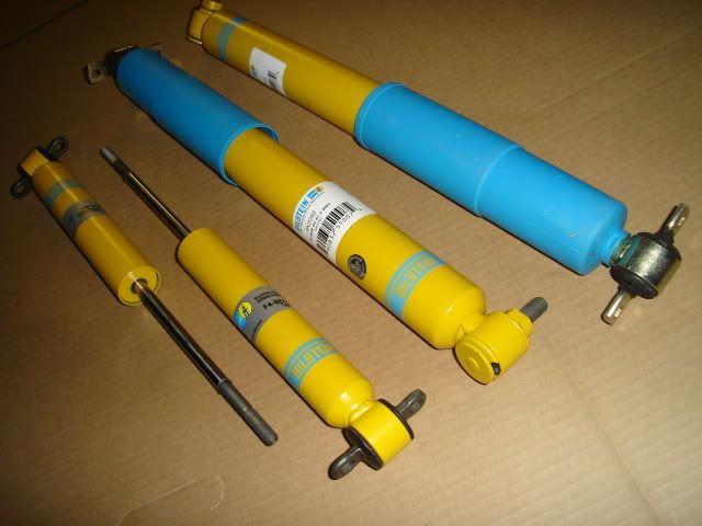
|
|
#2
09-11-2009, 01:07 AM
|
||||
|
||||
|
I did a little grinding on the driver's side upper control arm to provide clearance between the control arm pivot area and the top of the differential housing. Just goes to show that you need to pre-fit all of your new aftermarket components whenever possible.
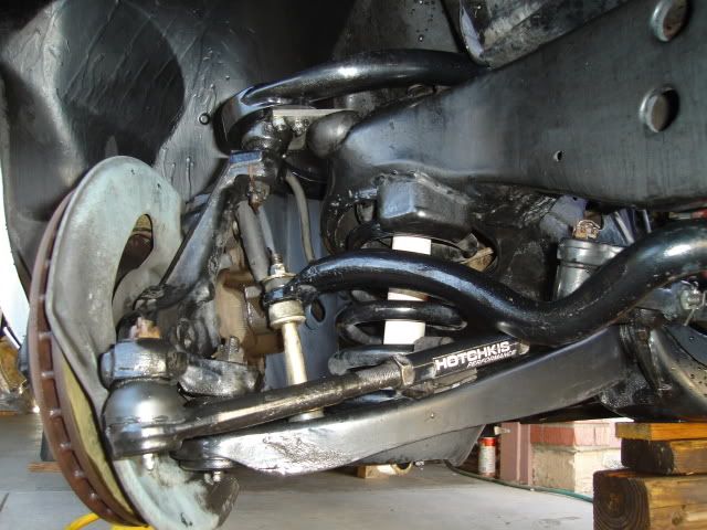
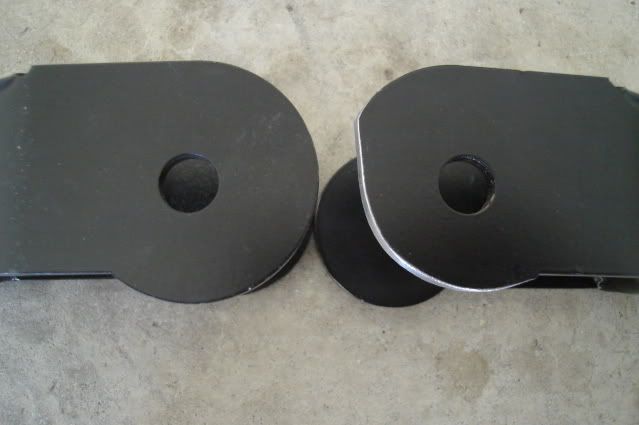 Here you can see the tight clearance between the arm and the housing after grinding. It's a bummer when you have to grind on a freshly powder coated brand-new component, some black enamel took care of the minor touch-up needed. 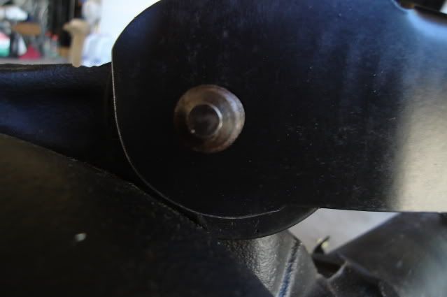 I took the threaded ends of the arms apart and added a little more moly grease to the threads, I was glad to see they came with a decent amount of proper lube on them. These parts almost look too pretty to hide up underneath the car. 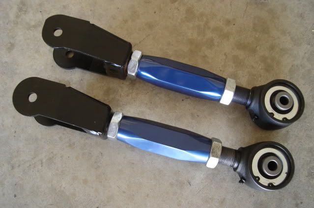 One of the drivetrain upgrades: A 3.42-geared Eaton posi-equipped '71 -'72 Buick A-body rear end with the Moser 30-spline axles. All of the KORE3 C6 Z06 rear brake adapter parts and internal parking brake components are laid out and ready. 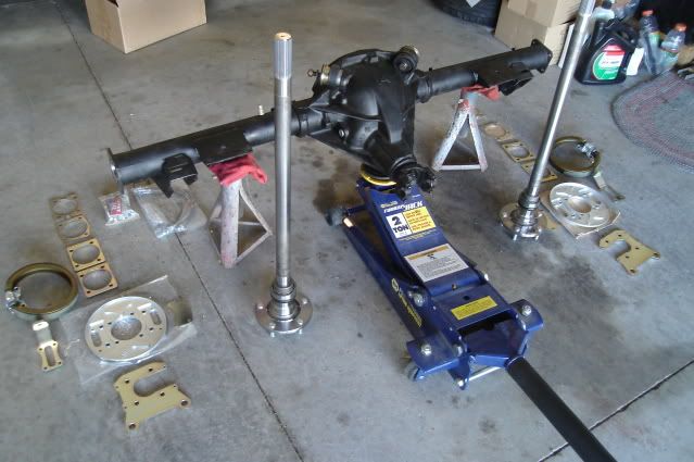 The KORE3 kit comes with all of the proper spacers and brackets necessary to make the Corvette brakes a true bolt-on installation. The fully-machined billet aluminum parking brake backing plates are a true work of art, this high-quality kit was worth every penny. 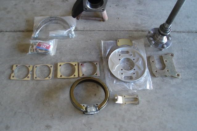 A look at the parking brake assembly before the rotor is installed. 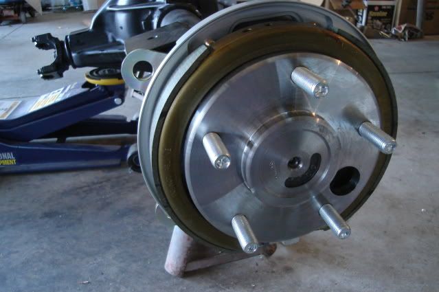 From the back side, the caliper and bearing retainer bracket is one piece. 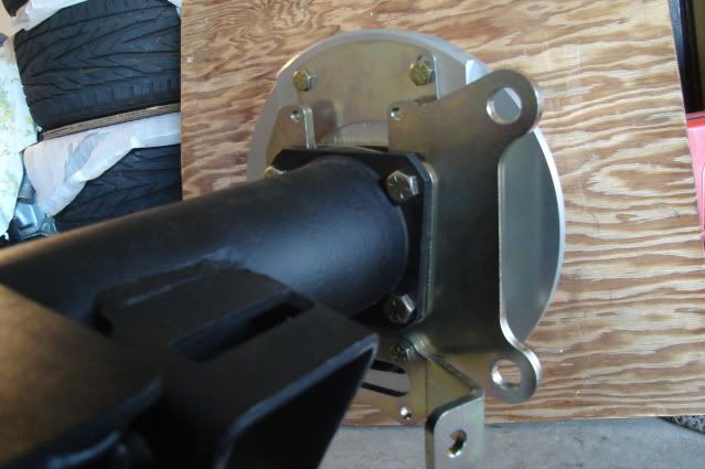 From the top you can see the series of spacers as they stack up to make everything fit. First a .105" thick spacer between the bearing retainer/caliper bracket and the housing end, next two .250" thick spacers between the retainer/caliper bracket and backing plate. Last there is a steel plate about .100" thick between the aluminum backing plate and the four 3/8-16 flanged self-locking nuts that hold everything in place. 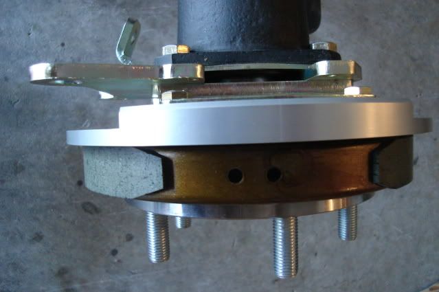 Both 13.4" rotors and 4-piston calipers are now installed to check for fit. These things are monsters!  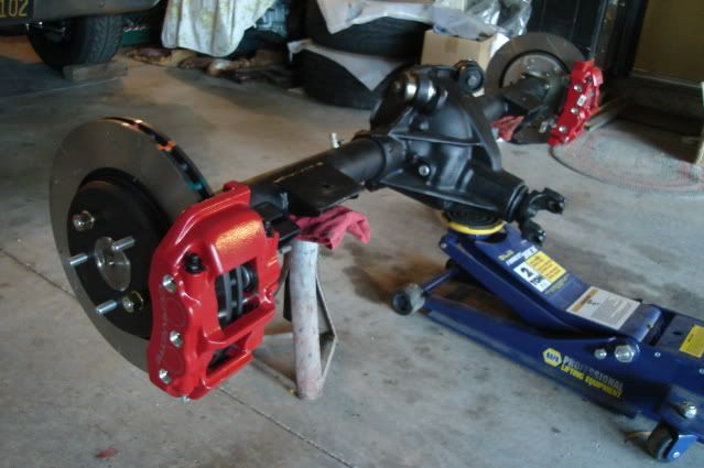 These should help haul this soon to be very fast Tempest down quickly. Good brakes = a safer car.  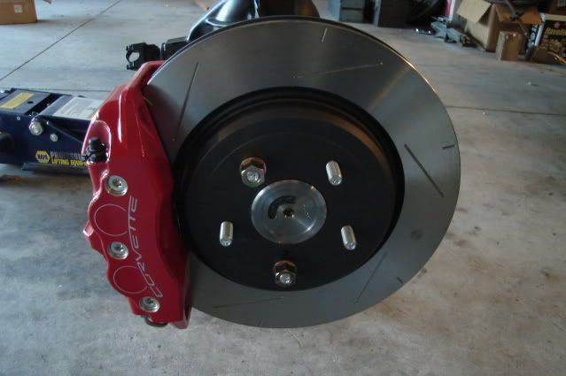 I stopped by the local Pep Boys and picked up a couple of 40" lengths of 3/16" brake line. I ended up using 33.5" of line on the driver's side and 36" on the passenger side, owning a decent flaring tool is a must when shortening pre-made hard lines or making up new ones. The difference in line length was due to the offset location of the brake line tee on the top of the differential housing. The 8.5 rear has a cast-in bolt boss on top that's tapped for 5/16-18 thread to mount the tee, unlike the 8.2 rear these cars came with that use a bracket attached to the top cover bolt to mount the tee. 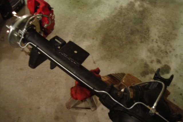 I bought some FlexKORE (TM) brake lines from KORE3 for the entire brake system to replace all of the flexible rubber lines, top-quality parts that will last forever and give better braking performance. I had to make sure that the FlexKORE lines were mounted in such a way that would allow the caliper to be pulled off the rotor for pad changes without disconnecting the lines. 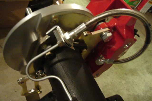 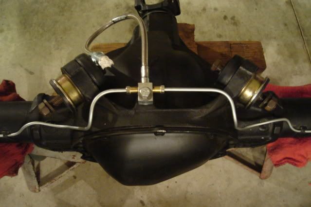 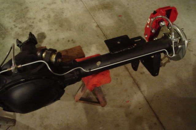 I filled the rear end with 2.5 quarts of Castrol 80W-90 gear oil (no synthetic for limited-slip units) and a 4oz bottle of GM #1052358 Limited Slip Additive, after 1000 miles I'll dump the oil and refill with new. With the gear lube taken care of and the brake lines completed the rear end finally ready to install. I pushed the Tempest out and laid out all of the rear suspension pieces: Currie Currectrac control arms, Global West S-60 springs, 1" rear sway bar, Bilstein shocks and some Hotckis mounting braces to reinforce the frame. I found that I was missing a couple of bolts that I needed for the Hotchkis mounting braces (used) so I headed to NAPA and picked up the Grade 8 bolts. I laid the new adjustable upper control arms next to the stock ones and slipped some bolts through them both. I adjusted the length on the new ones so they would match the stock ones to have a good baseline to start out with. I pumped all of the Johnny Joints and urethane bushings full of grease while I had easy access. 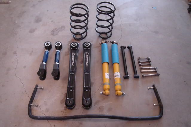 Out with the old. 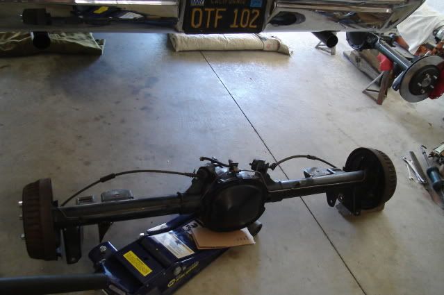 I had read about the tight fit of the Currie arms to the frame mounting points, and sure enough there was about .010" of interference. 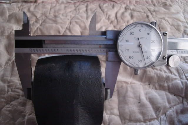 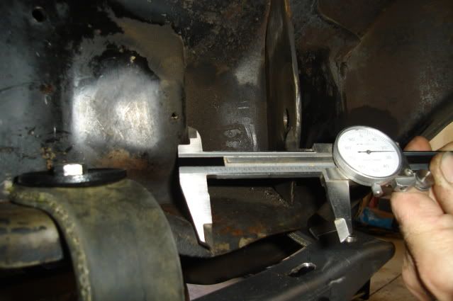 I used a slide hammer with a hook attachment and gave it about 3 hard knocks, this opened up the mounting bracket just enough for the clearance needed. The mounting points were crushed inward a little by previous tightening of the old suspension parts, it's not a big deal to open them back up again. 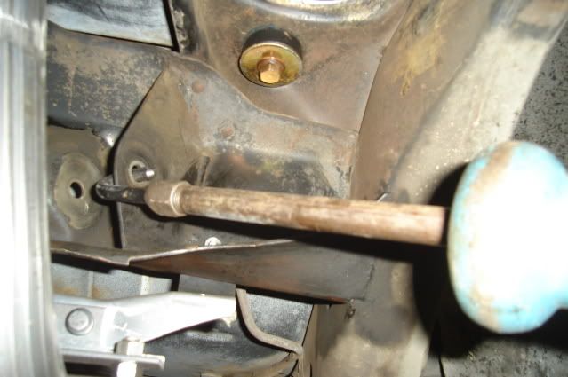 Control arms and mounting braces installed. On the lower arm on the pasenger side the very front end of the Currie arm interfered with the mounting bracket on the frame. I removed the arm and hammered the center of the mount in about 1/16" to get the clearance I needed. As you can see in the picture below, this was as low as the arm would pivot downward before doing the clearancing. You must remove the front grease zerk before installing these and put it back in when you're all finished, otherwise you'll break it off as the arm pivots down while putting the rear end in. 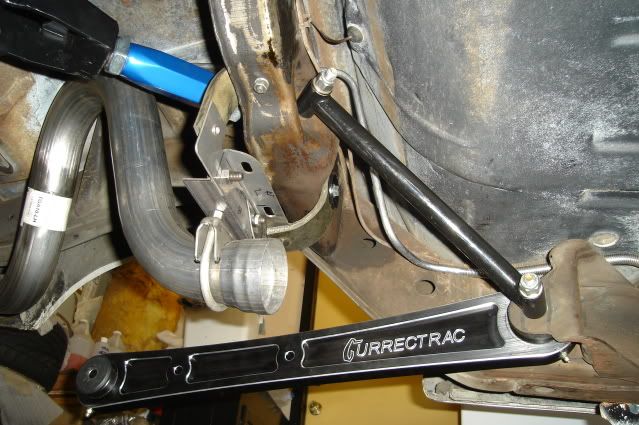 In with the new.  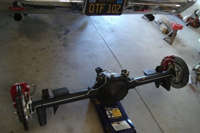 All buttoned-up. No sway bar installed yet nor any brake pads. 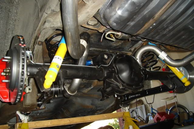 Suspension at full droop, shocks fully extended. 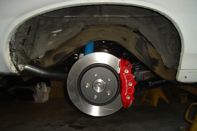 Rear end install complete, back down to earth. 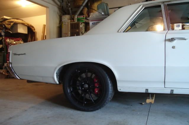 I'm really liking the contrast of the black wheels and the red Corvette Z06 calipers. Wheels are 18X9" O.Z. Racing Ultraleggera weighing in at only 20.8 pounds each bare, tire sizes are 275/40-18 rear and 245/40-18 up front. 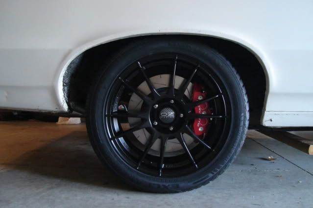
|
|
#3
09-11-2009, 01:16 AM
|
||||
|
||||
|
I put the Tempest up on two large 6-ton jackstands and removed the front wheels. The old suspension was cleaned up with some Simple Green, it's all still in nice shape. I cleaned and painted the frame from the firewall forward and the suspension with POR-15 semi-gloss black (using a paintbrush) about 10 years ago.
 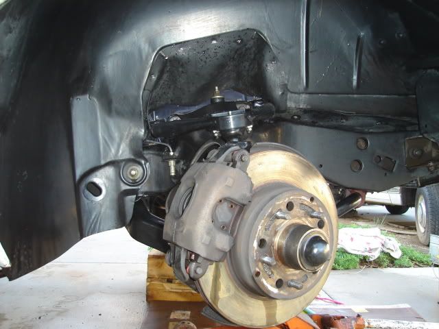 Next I removed both front shocks and the sway bar end links. I loosened up the tie rod adjusters, but left the tie rods attached for now so they would help keep the spindles from moving while loosening up all 4 of the ball joint castle nuts. After removing the cotter pins and loosening the ball joint castle nuts by a few turns I used a 12" long by 1" diameter brass bar as a drift to knock them loose from the tapered holes in the spindle. After only a couple of hard raps on the ball joint studs with a 2-pound hammer they popped right out of the spindle, against the loosened castle nut. The brass bar is long enough to do all of your hammering clear of the suspension parts, plus you can get a good swing with the hammer. 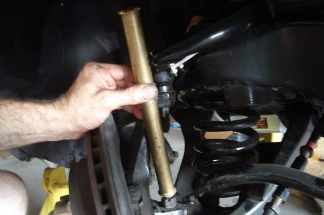 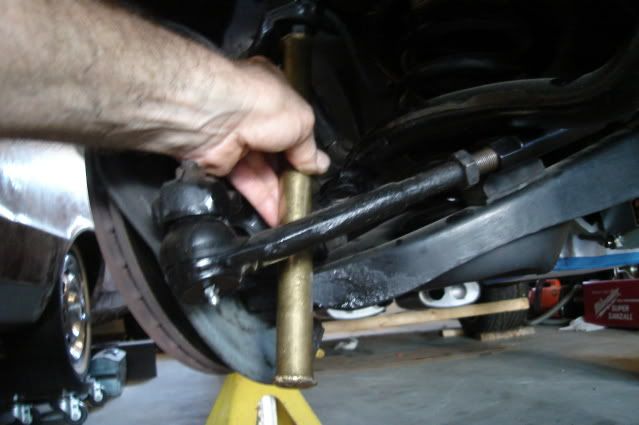 Next I put my floor jack with a 2X6 wood block underneath the control arm spring pocket and jacked it up enough to remove the tension against the castle nuts. After removing the castle nuts I let the jack down just enough to get the spindle assembly out, I disconnected the brake hose at the frame bracket beforehand. 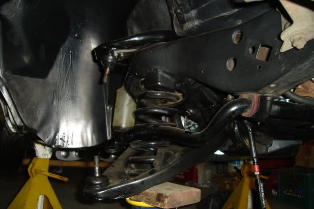 The H-O Racing front springs are fairly short and came out easily after letting the lower control arms all the way down with the jack, I didn't need to use a spring compressor. Having enough weight on the front end is the key to getting away without the need for a spring compressor, along with a short free-height spring. 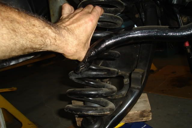 To get the upper control arms off I had to remove the rubber spash shields from the inner fenders to get enough room to maneuver them out. I also had to take the steering shaft loose from the rag joint coupler on the driver's side and push the steering shaft over as far as possible to get the control arm shaft off the 2 mounting bolts that are pressed into the frame. Tear down is now complete, all I need to do now is a little cleaning of the suspension attachment points on the frame and I'll be ready to start installing the new parts. 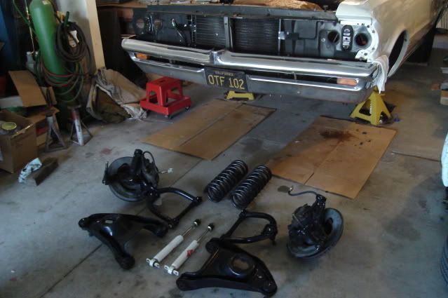 There's really nothing wrong with the old '78 B-body spindles with 12" rotors, reinforced stock lower A-arms and Hotchkis upper control arms with greasable poly bushings. They truly made a night and day difference in braking and handling over the original factory 9.5" drum brakes and rubber-bushed suspension pieces that had over 140K miles on them.  I'm replacing them all now with SPC adjustable upper control arms and tubular lowers, American Touring Specialties AFX forged aluminum spindles and C6 Z06 brakes with hopes that I'll see yet another night and day difference in braking and handling. New front suspension components laid out, I'll be reusing the H-O Racing front springs. 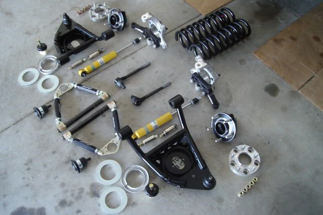 I laid the SPC upper control arms over the Hotchkis arms and adjusted the links to get them close to where they'll need to be. Before doing this I took the links apart and put a good coat of moly on the link threads. The curved rear tube on the Hotchkis arm interfered with my 18X9" wheel at near full steering lock, I'm hoping to gain some clearance at that point. The mounting holes in the new A-body Moog upper ball joints wouldn't line up with the two outward bolt holes in the SPC arms, those two holes are drilled a little too far apart. A little work with a rat-tail file to slot the holes inward by .020" each took care of the slight mismatch. The mounting holes are already drilled to .300" in the arms which is plenty of clearance for a 1/4" bolt. I didn't like having to file on my new control arms, but after thinking about how much I had to hammer the crap out of my trans tunnel to make my 4-speed auto overdrive trans fit it didn't seem so bad. 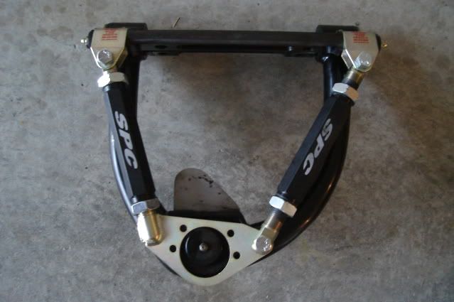 I bought some new hardware to attach the upper control arms to the frame, the billet aluminum cross shafts are drilled for 1/2" mounting hardware so the original 7/16" bolts wouldn't work. This gave me the opportunity to gain some additional clearance between the headers and the bolts, the new hardware is 1/2" shorter. 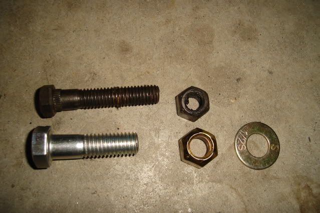 Upper control arm bolted in place. You have to bend the rear corner of the opening in the inner fender inward to clear the rear control arm pivot on the cross shaft, this slight modification was already done to make the old Hotchkis arms fit. 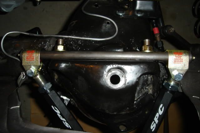 The bare aluminum AFX spindles and cast aluminum lower spring seats were treated with an aluminum cleaner (Alumiprep #33) with an alodine solution (Alodine #1001) to protect them from corrosion. You can buy them from Aircraft Spruce: http://aircraftspruce.com 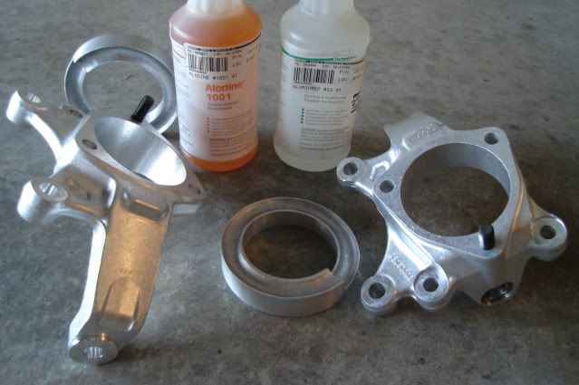 The SPC lower control arms went in easily using some new 1/2-13 Grade 8 hardware and nylock nuts, these arms already have a 1" drop built into them. After making sure the top of the spring was correctly clocked in the upper spring seat I dropped the aluminum lower seat into the control arm and made sure that it was clocked correctly as well. I was able to pull the lower arm up into position with the spring in place by hand and slide the jack underneath it, no spring compressor needed. 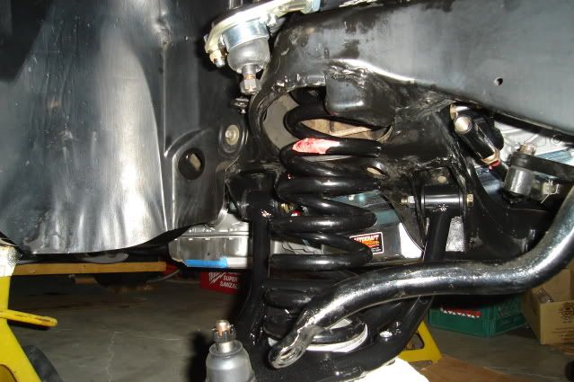 AFX spindle is now in place, there's just enough weight in the chassis to compress the spring so the ball joints would mate up with the spindle. The castle nuts on the ball joints were snugged lightly at this point. If I don't like the ride height after the car is fully assembled it will come apart easily so I can either cut the springs or add spring spacers under the spring seats. 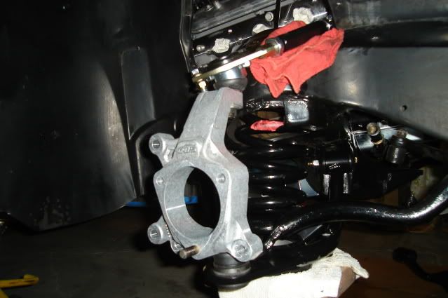 The billet aluminum ATS steering arms are now in place along with the Moog tie rod ends. Most of the major components are not tightened up yet, things will be coming apart a few times to make various adjustments. 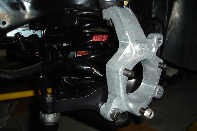 The front suspension assembly is complete enough now that I can see how everything is fitting up, it's looking pretty good at this point. 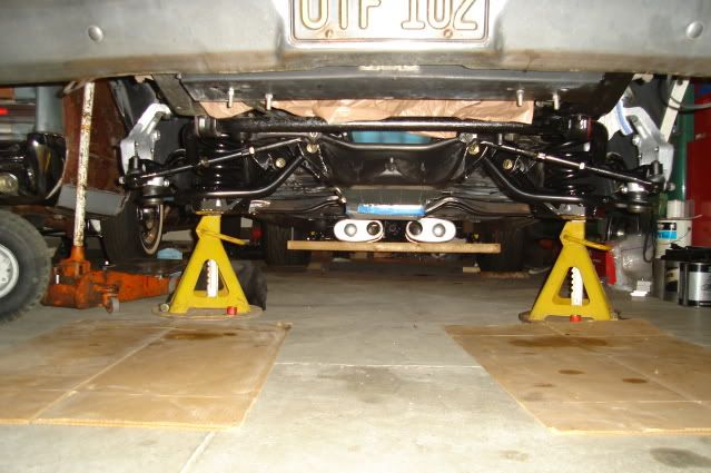 Next I have to get the SKF racing hubs prepared. For starters, the studs are too long. Since I'm using wheel adapters the studs need to be shortened to match the thickness of the adapters (1.063") plus the thickness of the front brake rotors (.300"). 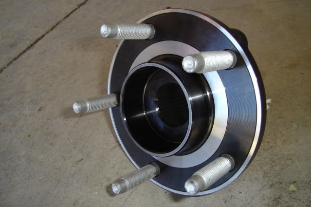 I ended up grinding about .400" off the ends of the studs. 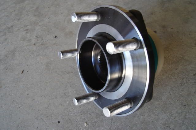 The AFX spindles use two bolts and one stud to mount the hubs. The hubs were designed to use 3 bolts so all three holes are threaded. In order to use the one bottom mounting stud on the AFX spindle I had to drill out the threads in one of the holes with a 1/2" drill bit. 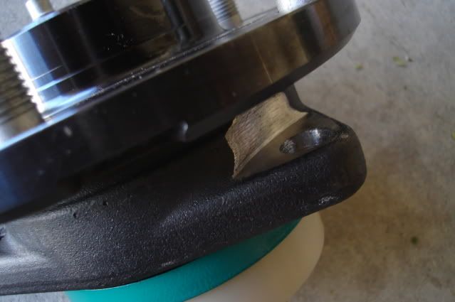 I had to use a die grinder with a cutting wheel to make some clearance for the nut to turn and to provide a flat area for it to tighten down onto. 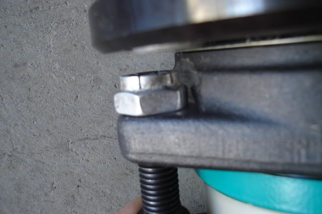 After having a lot of fun hacking on my new hubs they're now bolted in place. 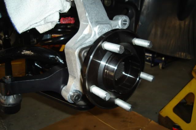 New 14" rotor and wheel adapter mounted up to the hub. The adapter solves two problems, converting the front bolt pattern from 5 on 4.75" (5 on 120.65mm) to 5 on 120mm and effectively reducing the backspacing on the wheel to 5.507" from 6.57". I had to grind about .060" off the ends of the lug nuts holding the adapter in place for clearance. 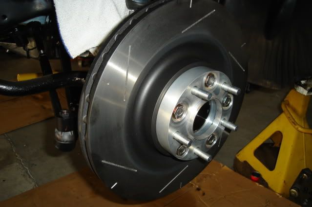 Bolted the wheel in place. No brake calipers yet, not enough time today with all the drilling and grinding going on. 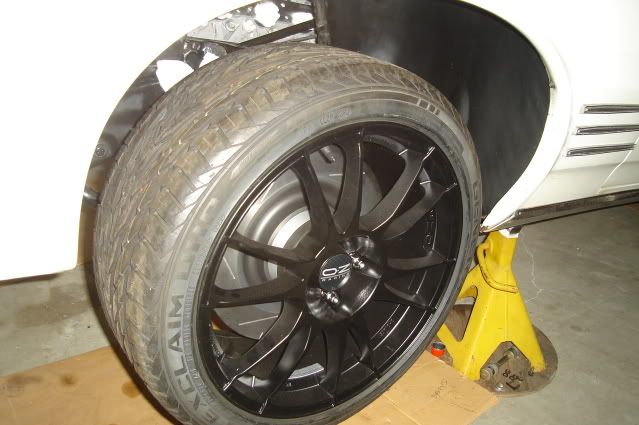 Looks like there's plenty of clearance between the upper A-arm and the inside of the rim with the wheel turned all the way to the left, the clearance here will increase with the car's full weight on the suspension. 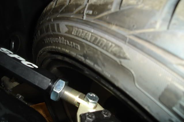 Set the car on the ground to see how it looks. I'm pretty happy with the ride height considering the amount of weight that still needs to be put back in the car. No seats, front or rear glass, most of the exhaust system out, no belt-driven accessories on the engine, no fluids in the engine or trans, no A/C compressor and no hood or right front fender. 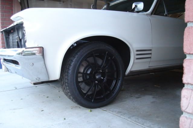 The AFX spindles have 1" of drop built in, combined with the 1" drop from the SPC lower control arms it's looking like I won't need to trim the front springs. 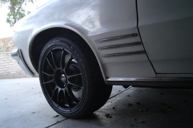 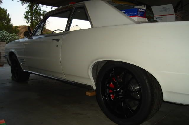 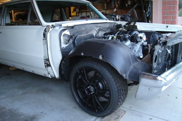
|
|
#4
09-11-2009, 12:36 PM
|
||||
|
||||
|
Very nice setup with premium parts. And your documentation/walk-through is excellent. Great work.
__________________
 "GTO......Gas, Tires and Overdraft"! "GTO......Gas, Tires and Overdraft"! '70 GTO convertible, 434, 4-speed |
|
#5
09-13-2009, 09:39 AM
|
||||
|
||||
|
Wow. Looks great!
__________________
Darin '64 Bonneville Wagon (sold) 69 Lemans-All motor (sold) 9.81 @ 136.39MPH |
|
#6
09-13-2009, 11:26 AM
|
||||
|
||||
|
I do not want to know what it all costs but are ya going to sell your old set up? And yes I have been on the end of no brake pedal.
__________________
72 GTO 400-M20 Lucy Blue 86 2+2 Black 09 G8 GT red 08 Torrent GXP (wife's) 09 G8 ST (UTE) black A pissed off fat house chimp on dope would be a lot more deadly. |
|
#7
09-14-2009, 12:58 AM
|
||||
|
||||
|
Thanks for the kind words guys.
After doing 'budget builds' most of the time on my projects I figured I'd do this one up as 'right' as I could afford to this (probably last) time around. Not that I haven't had great fun and good results while keeping the costs low over the years, I've never been unhappy doing things 'on the cheap'. The old front suspension is still in fine shape and ready to bolt on and go, however it was sold a few weeks ago to a local PY member. Shipping costs would have been a killer on this, even with me packing it all up for no added cost like I do with everything I sell off. I'll be sure to update this thread later on when I install the new GM 15/16" bore manual master cylinder and Wilwood adjustable proportioning valve, along with all the new plumbing necessary to make it all work. Costs involved so far for those interested: Front brake kit - $1136.50 Rear brake kit with internal parking brake - $1759.00 Lokar parking brake cables and hardware - $175.00 SPC front upper control arms - $340.00 SPC front lower control arms - $548.00 Cast aluminum lower spring seats and shim kit (ride height adjustment) - $58.00 Progressive Rate Jounce Bumpers - $26.90 ATS AFX forged aluminum spindles - $585.00 ATS billet aluminum A-body steering arms - $215.00 SKF racing hubs - $760.00 Moog upper ball joints - $50.00 Moog outer tierod ends - $70.00 H-O Racing Specialties front springs - $0 (20+ years old with 40K miles on them) Currie Currectrac adjustable upper rear control arms - $299.95 Currie Currectrac lower rear control arms - $389.95 Global West S-60 rear springs - $60.00 (unused new parts from private party) Hotchkis rear mounting braces - freebie Pro-built 8.5 corporate 3.42 posi rear end complete - $1734.00 O.Z. Racing Ultraleggera 18x9" wheels - $358.00 X 5 (spare wheel included) = $1790.00 5 new tires - $660.00 Front wheel adapters - $150.00 Bilstein shocks - $300.00 Energy Suspension polyurethane body to frame mounts - $120.00 That's covers most of it, add in about 500 dollars or so for shipping all of this stuff. The really hard-core A-body Pro-Touring guys pull the body off the frame and usually do one of 2 things: 1) Box the stock frame and reweld all of the factory weld seams, then send it out for sandblasting and powdercoating. 2) Toss the factory frame altogether and put an aftermarket frame under the car, with way better and much pricier suspension stuff than I'm using. There's always a better way to do it and a way to spend even more money as you know. This is just about it for me. 
|
|
#8
09-14-2009, 08:47 AM
|
||||
|
||||
|
Thats some serious $$$ invested, and IMO you've bought premium parts that will give you premium performance. The way you've documented each step and part as it goes to together is second to none. And I thought my documentation of each step I did to my car was good! The Schwartz or SRG frames are beautiful pieces of engineering, and yes, probably cheaper, but with judicous boxing and welding I think you'll come very close. I'm very impressed.
__________________
"GTO......Gas, Tires and Overdraft"! '70 GTO convertible, 434, 4-speed |
|
#9
09-15-2009, 01:27 AM
|
||||
|
||||
|
Looks great B-Man, Post a photo of that great TA you own also? TKS Randy.
|
|
#10
09-15-2009, 07:24 AM
|
||||
|
||||
|
Outstanding! Thank you!
|
|
#11
09-16-2009, 02:01 PM
|
||||
|
||||
|
Damn! That's some fine work!!
My only question is...when are you having a "Bring your car to my house and I'll help you install your new suspension/brake parts BBQ"? I'll pay for the grub and whatever liquid refreshments you want... 
__________________
The Firebird, GTO & LeMans are gone...the garage is now occupied by 2005 Porsche 997 C2S and more guitars in the house... |
|
#12
10-11-2009, 12:49 AM
|
||||
|
||||
|
.....for a while today and made some decent progress.
I removed the old master, it's a 1-1/16" bore 2nd-gen F-body disc/drum manual brake unit that worked very well with the single-piston B-body calipers. I'm replacing it with a 15/16" bore 1977 Monte Carlo or Malibu disc/drum manual master that comes complete with the pushrod, a $35 item with an $11 core charge (pictured below in the foreground). That's right, no power brakes. Of interest is the two masters are configured backward from one another. The F-body master has the front brake reservoir in front, the Monte master has the front brake reservoir located in the rear. This means I will have to remake the lines from the master to the combination valve. 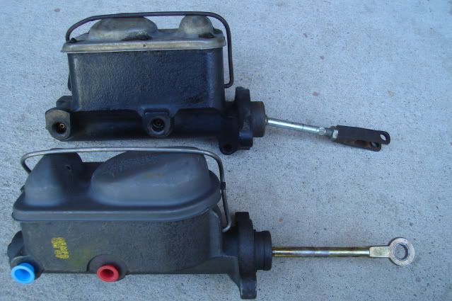 I was able to use the old 1964 Tempest single-master pushrod with the F-body master. For reference I measured from the mounting surface of the master to the center of the pushrod pivot pin, it looks to be right about 6". 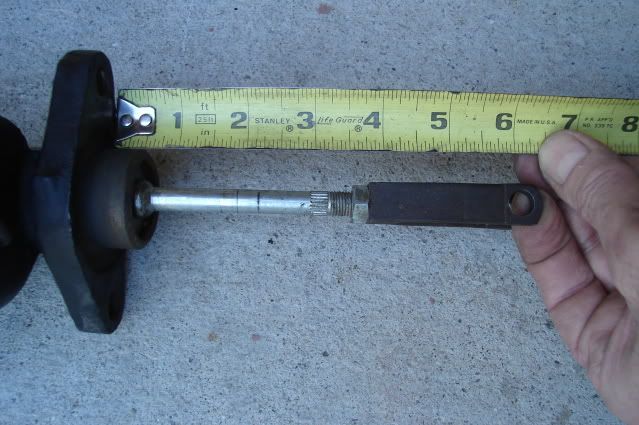 The new Monte Carlo master pushrod won't be quite long enough nor will it fit up to my brake pedal. It fits deep into the piston, by about an inch unlike the F-body master. 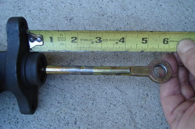 I will cut the new pushrod off at the cut line shown and thread it with a 3/8-24 die so it will screw in to the original Tempest brake pushrod clevis. It's just long enough to work. 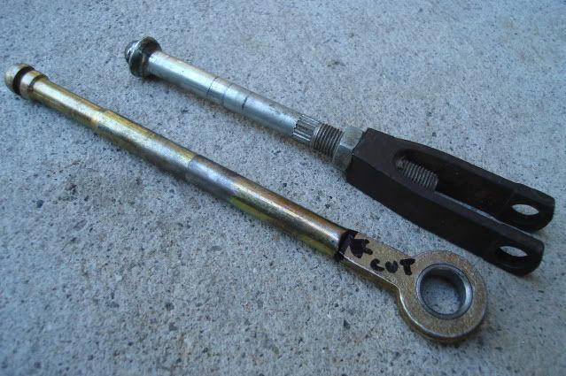 I will reuse the 2nd-gen F-body combination block and mounting bracket, the bracket has been slightly modified by bending the mounting tabs to tuck the combo valve up close to the master cylinder. The combo valve has been modified by removing the cartridge and spring (shown next to the end cap), they can be accessed after removing the end cap. The Wilwood adjustable proportioning valve ($42) will connect to the 3/16" brake line adapter fitting in the end cap, it's mounted on a simple angle bracket. I will adjust the front to rear brake bias using the Wilwood prop valve to prevent the rear brakes from locking before the fronts, especially under wet road conditions. 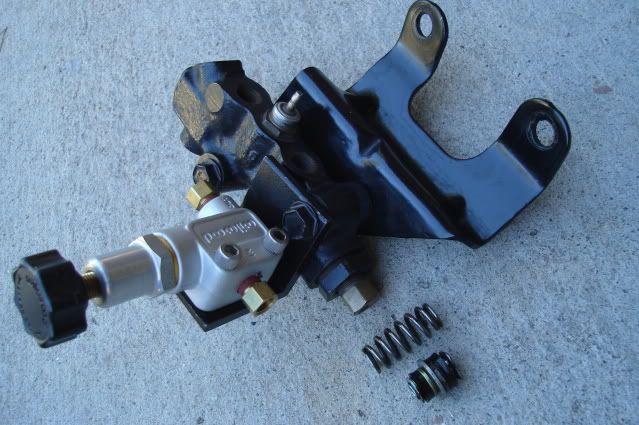 I made up some new lines from the master to the combo valve, plus a short loop to connect the adjusable prop valve to the combo valve. I was able to reuse and reconfigure the original factory 3/16" line from the front brake reservoir to the combo valve, but had to make up a new 1/4" line from the rear brake reservoir to the combo valve. All these lines were bent by hand, the tubing is pretty soft so it's not too hard on your thumbs. There's no way to use a tubing bender on these with the bends so close to the tube nuts. 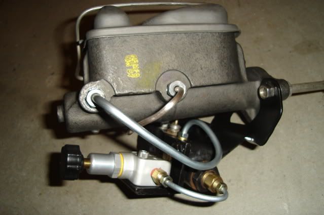 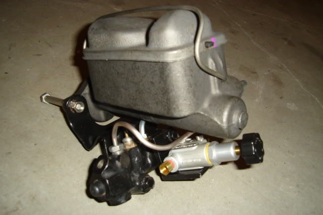 The completed assembly test fitted in place, the short loop from the combo to the prop valve clears the inner fender by about 1/2". 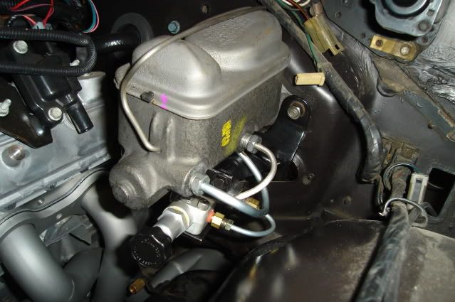 That's all for today.
|
|
#13
10-11-2009, 08:38 AM
|
||||
|
||||
|
Interesting you're using a disc/drum master (as I am). I got mine off a car with huge 11 x 2 rear drums so I figured the capacity would be close. I'm just curious as to how you came to that decision on your car. By the way, I'm not using a prop valve, I tee'd the fronts and then put an adjustable valve on the rears.
__________________
"GTO......Gas, Tires and Overdraft"! '70 GTO convertible, 434, 4-speed |
|
#14
10-11-2009, 09:28 PM
|
||||
|
||||
|
Quote:
Today I finished making up all of the hard lines for the brakes. Again all of the bends were made by hand, making for some pretty sore thumbs by the end of the day. 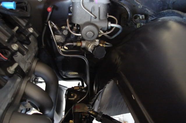 The lines coming down from the combo and prop valves were bent this way to leave room to pull the steering column in and out of the car. The line in front leads to the left front brake, the next one (60" long) goes under the engine along the front crossmember to the right front brake and the rear line coming off the prop valve connects up to the original rear brake line. 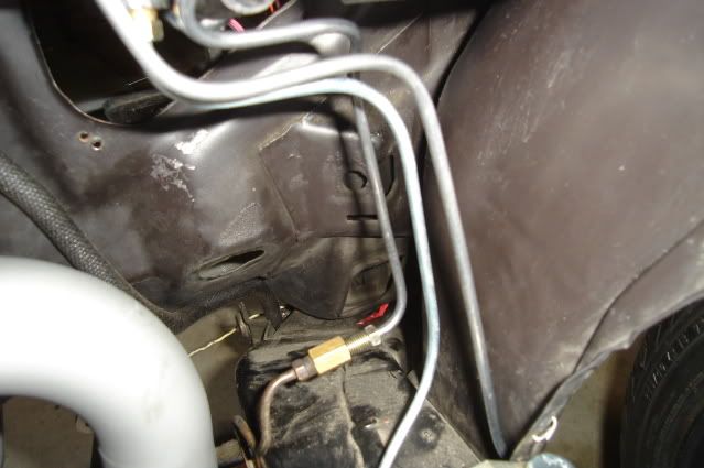 The 60" long line running under the engine terminates here, getting this line bent and routed was made a little easier with the inner fender out of the way. The engine will come out once more later on, I will tidy up the bends a little and fasten it down better at that time. 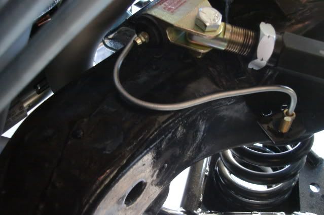 Another job out of the way that will bring me a bit closer to driving this old heap. Keepin' on it.
|
|
#15
11-28-2009, 03:31 PM
|
|||
|
|||
|
Anything new on this project?
|
|
#16
11-28-2009, 05:49 PM
|
||||
|
||||
|
Bart, after re-reading this post, it really is kind of funny how similar our suspension builds are! Same rear end, same shocks, same rear upper and lowers, same front uppers and lowers. I think just about the only difference is that I'm going with stock spindles and Baer brakes. If I remember right, you had a Lee power steering box and pump too. Are you going to be able to use those with the new motor?
Go figure that we live within walking distance of each other...
__________________
Sammy 1967 Lemans: 455 swap in progress (stock crank, stock rods, TRW slugs, mildly ported 6x heads, Stump Puller hyd roller, 1.5 PRW aluminum rollers, Comp hyd roller lifters, Performer RPM, q-jet, RA exhaust manifolds, 2 1/2" exhaust, ebay HEI), 200 4R, and some suspension stuff |
|
#17
11-28-2009, 08:46 PM
|
||||
|
||||
|
No more progress on the suspension lately. There are so many other things going on with this project, I was happy to finish mocking up all of the suspension parts and get the car rolling on 4 wheels again.
I still need to mess around with the tie rod adjusting sleeves and center the steering wheel. One of the sleeves is giving me a hard time, one of the tie rod ends won't screw in deep enough to allow me to make both tie rods close to equal length. The hardware on just about the entire front end needs to be tightened up. None of the brake pads have been installed yet, and the emergency brake cables (Lokar universal) need to routed and mounted up. All of the flexible brake lines need to be hooked up so I can bleed the brakes. After the brake lines are all connected the master cylinder needs to come off and get a good bleeding on the bench and get reinstalled. I need to get all of the accessories mounted on the engine so I can have a power steering pressure line made up. I'll be using the 2008 Corvette power steering pump (the engine is a 2008 LS3) and my trusty 20-year old Lee Power Steering 12.7:1 box. Lots of stuff to do, big project. |
|
#18
12-08-2009, 02:04 PM
|
|||
|
|||
|
As usual, your information is extremely helpful to me as a first-timer in a lot of this stuff. My '64 and I are really fortunate to have a mentor like you available to save the car from damage and me from more blood loss than is required.
(I usually bleed a little on my projects. It's kind of a stamp of completion.)
__________________
Hmmm.. Now WHERE did this part go??? |
|
#19
02-04-2010, 09:24 PM
|
|||
|
|||
|
What was the reason you chose to go manual master cylinder(non power)? Do the large diameter rotors make the manual seem like power brakes?
So you have a 12.7:1 power steering box. How does that compare to the stock box?
__________________
If someone else can design it, I can sure figure out how to fix it. |
|
#20
02-04-2010, 11:09 PM
|
||||
|
||||
|
Quote:
The 12.7:1 box is a high-effort unit that gives you a lot of 'feel' in the steering wheel, not loose-feeling and easy to turn with one finger like the stock power box. One of the best upgrades you can make for enhancing your driving experience, with about 2.5 turns lock to lock driving and parking in the city is a lot easier. The quicker steering ratio doesn't make the car feel 'twitchy' on the the highway, always feels nice and steady. |
| Reply |
|
|
The PY Online Forums is the largest online gathering of Pontiac enthusiasts anywhere in the world. Founded in 1991, it was also the first online forum for people to gather and talk about their Pontiacs. Since then, it has become the mecca of Pontiac technical data and knowledge that no other place can surpass.


 Linear Mode

