


| FAQ |
| Members List |
| Social Groups |
| Calendar |
| Search |
| Today's Posts |
|
#21
 02-26-2016, 12:48 AM
|
|||
|
|||
|
Hey Larry, get a load of this !! Reverse flow on a 455 !
http://image.hotrod.com/f/38825464+w...n%2bengine.jpg |
|
#22
02-26-2016, 10:36 PM
|
||||
|
||||
|
That's a 455? They dressed it up nicely to look '57 Pontiac. Heads give it away as not being '57 though. I wonder if they used the distributing tubes in the heads.
|
|
#23
03-07-2016, 01:07 AM
|
|||
|
|||
|
Pretty cool PCV system. The road draft tube has to be open to evacuate the crankcase. It looks like the left valve cover is pulling air into the aircleaner and the right side is connected to vacuum. If there was no open draft tube on this setup there would be no way to pull air INTO the engine since the valve covers are both under vacuum.
|
|
#24
03-07-2016, 01:18 AM
|
|||
|
|||
|
Quote:
|
|
#25
03-07-2016, 01:38 AM
|
|||
|
|||
|
Yep but that's how his system is working.
|
|
#26
03-07-2016, 04:00 AM
|
||||
|
||||
|
Quote:
__________________
1960 Bonneville 2dr HT 389/400ci 363hp 1965 Bonneville 2dr HT 455/501ci stroker 600hp+ |
|
#27
03-07-2016, 04:07 AM
|
||||
|
||||
|
Quote:
__________________
1960 Bonneville 2dr HT 389/400ci 363hp 1965 Bonneville 2dr HT 455/501ci stroker 600hp+ |
|
#28
03-07-2016, 07:05 PM
|
|||
|
|||
|
Early emissions stuff is interesting to me so I looked pretty carefully through the 60 and 61 chassis manuals I have here. The 60 manual makes no mention at all about a "positive crankcase vent" system. It has the typical drawing of the road draft tube with the arrows. What is interesting though is the 61 manual has that same picture with the draft tube and arrows showing flow. But in the fuel chapter there is a 2 page system that describes removing the draft tube and installing a PCV system similar to the one pictured. The parts don't look the same, the big difference being the fresh air enters one valve cover through a regular breather, rather than the flat piece attached to the air cleaner as pictured. So for 61 at least, this must have been a dealer installed accessory package of some type. Need someone with access to Craftsman News archives from that time. It has the "factory" look to me and looks like it has been on that car forever. The 61 service manual instructs to remove the draft tube when installing the "PCV" system. Possibly the car in question had a dealer installed system installed incorrectly?
|
|
#29
03-07-2016, 08:22 PM
|
|||
|
|||
|
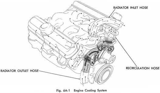
As far as the heater hose routing goes......per my 1960 HVAC manual the top heater core connection goes to the lower radiator connection point and the lower heater core connection goes to the "elbow" connection that's on the front of the passenger side head. The manual shows the lower heater core connection going to the top of the intake manifold but that's incorrect unless there was a running change made, as my car is not that way. Maybe it was a holdover diagram from 1959? The actual routing of the heater hoses goes thru a sheet metal loop or band that is on top of the cross member, if that is of any use.
|
|
#30
03-07-2016, 09:02 PM
|
|||
|
|||
|
Quote:
|
|
#31
03-07-2016, 09:10 PM
|
|||
|
|||
|
Quote:
http://image.hotrod.com/f/10612632+w...a%2Bengine.jpg Last edited by U47; 03-07-2016 at 09:16 PM. |
|
#32
03-07-2016, 10:04 PM
|
|||
|
|||
|
I found a blurb on a Cadillac forum stating that California cars prior to 1961 had no emission gear . 1955 to 1960 cars had to be retrofitted with emissions parts if the car changed registered owners. No way to verify but kind of makes sense.
|
|
#33
03-07-2016, 10:13 PM
|
|||
|
|||
|
Quote:
What we had were a hole bunch of cars that got terrible mileage and overheated. They, Ca. government, retracted the law after countless Ca. residents lost their engines. |
|
#34
03-07-2016, 11:09 PM
|
|||
|
|||
|
Ahhh... Graet when the gov gets involved and fixes the world for us, only to figure out they were wrong. Do you think the setup on the OP's 60 was a Pontiac dealer retrofit ?
|
|
#35
03-07-2016, 11:45 PM
|
|||
|
|||
|
U47, understand the clarification so my question would be: Do you think the OP's car has a dealer installed system?. Also, should the draft tube have been removed when they put it on?
|
|
#36
03-07-2016, 11:55 PM
|
|||
|
|||
|
Quote:
|
|
#37
03-08-2016, 05:24 AM
|
||||
|
||||
|
Thanks again for all the feedback! I 'll probably just block of the road draft tube for now and remove it later if I rebuild the engine. My engine has the "elbow" on the front of the passenger side head and no connection on the intake manifold like the 1960 Shop Manual shows. I found this photo that I think is correct way to mount the heater hoses?
__________________
1960 Bonneville 2dr HT 389/400ci 363hp 1965 Bonneville 2dr HT 455/501ci stroker 600hp+ |
|
#38
03-08-2016, 12:09 PM
|
|||
|
|||
|
Quote:
|
|
#39
08-01-2022, 09:05 PM
|
||||
|
||||
|
Well.....6 years later...if anybody is still tuned in.
A friend recently bought a 61 Bonneville...... He brought it by last week....and it appears to be leaking a fair bit of dirty oil from the crankcase vent tube... The 389 appears to be original...and runs great....no tailpipe smoke... It didn't appear to have a filter on the vent tube...but I can't see a filter helping much with this.. Need to investigate further.......could there be a baffle in the lifter gallery that was left out/off..? The valve cover breather caps appear to be original style.. Just looking for some input before I investigate. |
|
#40
08-01-2022, 09:44 PM
|
|||
|
|||
|
When I got my 61 I just pulled the draft tube and put in a gromet for the PCV and just used it like later engines.FWIW,Tom
|
| Reply |
|
|
The PY Online Forums is the largest online gathering of Pontiac enthusiasts anywhere in the world. Founded in 1991, it was also the first online forum for people to gather and talk about their Pontiacs. Since then, it has become the mecca of Pontiac technical data and knowledge that no other place can surpass.


 Linear Mode

