


| FAQ |
| Members List |
| Social Groups |
| Calendar |
| Search |
| Today's Posts |
|
#21
 03-11-2014, 12:22 PM
|
||||
|
||||
|
So the guy who had the car before you took the power antenna out but left the cable, the harness and the mount? Odd. He must have planned on having it fixed and putting it back in, but it never happened I guess. Interesting thing from your pic is that the antenna coax has a female connector on the end of it. The cable that came with mine also has a connector like that at the antenna and I had just assumed that the male part was broken off of it. But apparently that's the way it's supposed to be. Good thing I saw your pic before I went and bought a male connector, snipped the original female one off and then tried to install the new one....that would have been bad news to find out later that the connector was correct.
I'd like to see a pic of your finished installation whenever you get a chance. My next project is a 67 basket case 242 goat convertible and I am going to put some nice add-ons like a power antenna that works off the on-off switch to the radio. Now, I just have to figure out how to plug this one I have in to where?
__________________
Save yo Confederate money, boys, the South is gonna do it again! Pecosbill |
|
#22
03-11-2014, 12:50 PM
|
|||
|
|||
|
Will post more pics when I can of the final install of my elchepo antenna.
The car is stuffed away for the winter. I hope to have it out in April. I have pics of an original antenna. When I saw the connector on the antenna the cable made sense as well as the mount. Found a few more pics that I had saved and stuffed away on my computer.       
|
|
#23
03-11-2014, 02:12 PM
|
||||
|
||||
|
Great pics, thanks! The harness coming off of the switch is much longer than what I have on mine and the power plug is different. Otherwise, everything else is spot on.
__________________
Save yo Confederate money, boys, the South is gonna do it again! Pecosbill |
|
#24
05-05-2014, 09:08 AM
|
|||
|
|||
|
A few more pics I promised a while back.
This is the pick of the el-chepo antenna that I'm going with 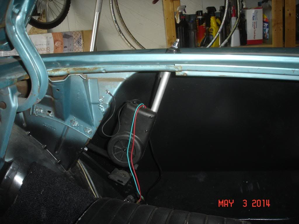 There were two clips behind the seat. 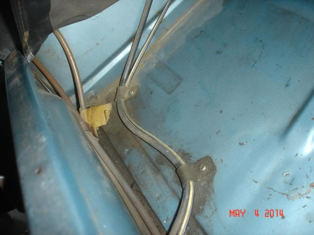 The old switch has seen better days and will not be going back in. 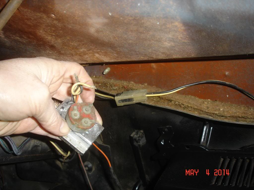 The orange power wire is plugged into the bottom right hand side. I would guess that is not factory correct. 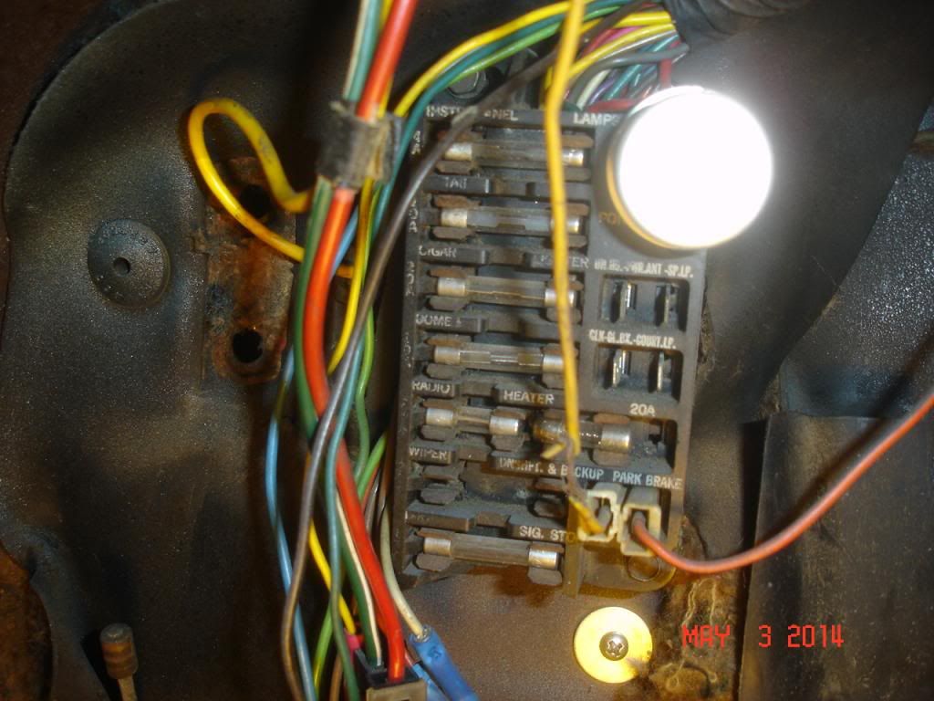
|
|
#25
05-31-2014, 12:33 PM
|
|||
|
|||
|
I would like to expand on the routing of wiring to the rear trunk area. The 2nd photo in Post No. 5 shows the antenna wire and power wire (wires) running diagonal and adjacent to the propeller shaft tunnel, feeding into the main floor channel. I have seen illustrations showing the wiring running in the diagonal channel just to the right in this same picture. However, typically what I have found is the wiring drops vertically down from the dash into the main channel. The main channel is provided with a series of rectangular bump-outs spaced at 9 - 13 in. intervals. These bump-outs are installed along the length of the main channel, often alternating sides, and sometimes opposite another. As seen in this same photo, the bump-outs are provided with dimples. The dimples are locators for the installation of the screws which are used to secure the retaining clips. Because you have power running to the trunk area, the Floor Pan Wire Protector Cover (cover) is used (Item no. 12 in Post No. 7). The cover is galvanized, and is used wherever you have power wire running to the trunk. The wires run up out of the interior, into the trunk, and secured as shown in the 2nd photo of Post No. 24, running between the wheel housing and quarter panel to the antenna.
I am not familiar with the two brackets in the 1st and 2nd photo of Post No. 5 which appear to be welded to the floor pan. For speaker wiring (Separa-Phonic) running to the trunk area where power is not involved, securement is not the same. While the route taken in the right side main floor channel is the same, 2 in. wide, 3-4 in. long, black tape is used to hold the wire in place. A single clip secured to the floor in the first bump-out behind the right side bucket seat may be used. All remaining securement to the floor is by tape. Because no power is involved, no galvanized cover is used. The wiring is secured to the diagonal bracing behind the rear seat, using two clips. |
|
#26
03-04-2018, 08:38 PM
|
||||
|
||||
|
Rohrt, I know this is an older thread, but my Tempest is nearing the point of wiring the power antenna that I'm adding. I would like to wire it correctly. Would you be willing to re-post your photos since photobucket has hijacked all the pictures? I know its asking a lot. Thanks in advance.
Tony |
|
#27
03-04-2018, 09:18 PM
|
||||
|
||||
|
After I did the fix suggested in another thread, the Roht pics are showing up in Posts #22 and Post #24 for me anyway.
Tom V.
__________________
"Engineers do stuff for reasons" Tom Vaught Despite small distractions, there are those who will go Forward, Learning, Sharing Knowledge, Doing what they can to help others move forward. |
|
#28
03-04-2018, 10:04 PM
|
||||
|
||||
|
Quote:
|
|
#29
01-23-2022, 10:00 AM
|
||||
|
||||
|
Hello all, I would like to follow up on this thread as I searched and it’s the only one that hit “power antenna routing”. If there is another thread could someone point me to it?
I have a correct Pontiac rear power antenna installed on my 65 GTO, but the power wiring is just running across the two “hooks” on the top of the rear seat back frame, then down the floor drivers side and appears under the carpet over by the parking brake area at the front. The antenna cable is just routed over the hump and down on the floor pan under rear pass seat area, coiled up/not connected. Likely because the antenna end is kind of chewed up with no center cable showing. The antenna works perfectly raising/lowering when connected to power. 1) looking at these pix in this thread and with my interior fully assembled with console, what is my best approach to route the antenna and power harness to the radio and (future) dash switch? Should I just bundle them together and snake under the carpet under the console or is it better to try to run a correct path. If correct, is the power wiring run separately through the wiring channel under the drivers seat, or do they stay together like it looks for these 64 pictures? 2) I plan to buy a correct NOS dash antenna switch with a new Ames bezel/handle and install when I pull the dash this summer for other things. I assume the plastic two-wire antenna power connector with black and white wires just plug straight into a correct under-dash switch wiring harness? 3) at the antenna cable radio end, is that supposed to be a male “standard” 50 ohm connector to plug into the back of the radio (AM/FM push button)? If so, do I need to just strip it back until I hit the center wire and then crimp a new connector on and should be good to go? Thanks for any help and discussion! I’ll post pix if that helps. I have the rear seat out and am preparing to pull drivers/passenger seat(s), console, seat belts, carpet etc to get a good path to the front. I’m now also considering installing a rear speaker while doing all this and would like to route that correctly too, nothing is back there right now. I figure I should get this all done at the same time. Fun stuff! Last edited by tallrandyb; 01-23-2022 at 10:03 AM. Reason: Wording |
|
#30
02-01-2022, 02:38 PM
|
||||
|
||||
|
Quote:
So questions are: 1) where exactly does this wiring protector mount? Under passenger side rear seat area? 2) where should you route the rear speaker wire to get it down to the protector from the trunk area? I know there are a couple of "clip" like hooks on the seatback framing, do I use one of those? 3) I'm also running power antenna wiring and cable under this protector, how should they route from the rear antenna (I assume over the wheelwell then just curve over towards the center until they reach the protector? The 64 rear antenna wiring pictures show them being held down by individual screws/brackets themselves). 4) Once all this wiring extends past the front of the protector towards the front, do I just tape it all down in a "channel" all the way to the dash? Wiring will be: antenna cable, antenna two-wire harness, rear speaker one-wire harness, and a single-wire cable for rear camera. Thanks for any help!! |
|
#31
02-01-2022, 03:19 PM
|
||||
|
||||
|
Was your 65 Originally ordered with a Power Antenna?
If so, there should be holes or possibly dimples in the floor on the RH side under the rear seat cushion. Here are some photos of a OEM Power Antenna that was ordered with my 65. MPC illustration showing metal protector for various rear mounted options. A spare factory unit I have. Red arrows pointing to both ends of protector which is covered by factory insulation. Routing of cable, wires and rear seat speaker blue wire. Chris.
__________________
1) 65 GTO Survivor. 43,440 Original Miles. Factory Mayfair Maize Paint with Black Pinstripe, Black Cordova Top, Black Interior, OEM Numbers Matching Powertrain. Purchased from the Lady that bought it new. Baltimore Built (11A). 2) 66 GTO Survivor. Factory Cameo Ivory Paint with Red Pinstripe, Red Interior. OEM Numbers Matching Powertrain. Tri-Power (OEM Vacuum Linkage), Automatic "YR" code (1759 Produced). Fremont Built (01B), with the Rare 614 Option. |
| The Following User Says Thank You to 60sstuff For This Useful Post: | ||
|
#32
02-01-2022, 03:23 PM
|
||||
|
||||
|
A few more showing how the cable and wires head over to the Power Antenna secured with clips.
__________________
1) 65 GTO Survivor. 43,440 Original Miles. Factory Mayfair Maize Paint with Black Pinstripe, Black Cordova Top, Black Interior, OEM Numbers Matching Powertrain. Purchased from the Lady that bought it new. Baltimore Built (11A). 2) 66 GTO Survivor. Factory Cameo Ivory Paint with Red Pinstripe, Red Interior. OEM Numbers Matching Powertrain. Tri-Power (OEM Vacuum Linkage), Automatic "YR" code (1759 Produced). Fremont Built (01B), with the Rare 614 Option. |
| The Following User Says Thank You to 60sstuff For This Useful Post: | ||
|
#33
02-01-2022, 07:08 PM
|
||||
|
||||
|
Hi Chris. Are those clips the same as the ws washer hose clip used on the dr. fender? Thanks
"Bill"! |
|
#34
02-01-2022, 08:41 PM
|
||||
|
||||
|
Quote:
Now it looks like I need the clips and hold downs for the speaker wire, so Ill start tracking those down. I appreciate it, great reference pictures! |
| The Following User Says Thank You to tallrandyb For This Useful Post: | ||
|
#35
02-02-2022, 10:20 AM
|
||||
|
||||
|
Quote:
The single metal clip that holds the hose for the W/S washer is larger and Ive never seen that clip used anywhere else on these cars. The clips in the trunk to secure the speaker wire and Power Antenna wires is smaller and a different design. Chris.
__________________
1) 65 GTO Survivor. 43,440 Original Miles. Factory Mayfair Maize Paint with Black Pinstripe, Black Cordova Top, Black Interior, OEM Numbers Matching Powertrain. Purchased from the Lady that bought it new. Baltimore Built (11A). 2) 66 GTO Survivor. Factory Cameo Ivory Paint with Red Pinstripe, Red Interior. OEM Numbers Matching Powertrain. Tri-Power (OEM Vacuum Linkage), Automatic "YR" code (1759 Produced). Fremont Built (01B), with the Rare 614 Option. |
| The Following User Says Thank You to 60sstuff For This Useful Post: | ||
|
#36
02-02-2022, 05:37 PM
|
||||
|
||||
|
Quote:
So, in looking at your two pix showing clips being used for the radio wire and power antenna wiring, the closest thing I can find appears to be this clip from Ames (D203). Is there a better source for the proper clips to use in the trunk for this stuff? Thanks! |
|
#37
02-02-2022, 05:42 PM
|
||||
|
||||
|
And now googling around I found this link:
https://www.zoro.com/b-line-by-eaton...14/i/G1951092/ With examples that look like they may be closer to correct. I assume anything that has enough of a "pinch" to hold onto the back brace or wheelwell seam/etc should work fine, it looks like the ones in your pix may be zinc also? Thanks! |
|
#38
02-03-2022, 04:09 PM
|
||||
|
||||
|
The cable clips you found on that ZORO site look pretty close.
The wire harness for the rear lights seems to have a similar clip that grabs onto a body seam. Here are a few more pics to work with.
__________________
1) 65 GTO Survivor. 43,440 Original Miles. Factory Mayfair Maize Paint with Black Pinstripe, Black Cordova Top, Black Interior, OEM Numbers Matching Powertrain. Purchased from the Lady that bought it new. Baltimore Built (11A). 2) 66 GTO Survivor. Factory Cameo Ivory Paint with Red Pinstripe, Red Interior. OEM Numbers Matching Powertrain. Tri-Power (OEM Vacuum Linkage), Automatic "YR" code (1759 Produced). Fremont Built (01B), with the Rare 614 Option. |
|
#39
09-05-2022, 12:20 PM
|
||||
|
||||
|
Thanks for the help and reference posts on the forum. Here are some pix:
First two: how I found the wiring in the car (wrong, power antenna wiring snaked over/under driver side, power antenna cable just looped under pass rear seat maybe because the radio connector was broken/missing). Next two: How I routed wiring and installed under-pass-rear-seat shield and screwed down and taped the wiring heading to the front. Last one, view back to front of all the wiring. The bundle contains the power antenna cable, the power antenna wiring harness (two-wire), the rear speaker wire, and a rear camera cable. Thanks for the all the help, I tried to get it all as close to correct as I could. |
| The Following User Says Thank You to tallrandyb For This Useful Post: | ||
|
#40
09-05-2022, 12:47 PM
|
||||
|
||||
|
Nice job. Looks good!
__________________
1) 65 GTO Survivor. 43,440 Original Miles. Factory Mayfair Maize Paint with Black Pinstripe, Black Cordova Top, Black Interior, OEM Numbers Matching Powertrain. Purchased from the Lady that bought it new. Baltimore Built (11A). 2) 66 GTO Survivor. Factory Cameo Ivory Paint with Red Pinstripe, Red Interior. OEM Numbers Matching Powertrain. Tri-Power (OEM Vacuum Linkage), Automatic "YR" code (1759 Produced). Fremont Built (01B), with the Rare 614 Option. |
| Reply |
|
|
The PY Online Forums is the largest online gathering of Pontiac enthusiasts anywhere in the world. Founded in 1991, it was also the first online forum for people to gather and talk about their Pontiacs. Since then, it has become the mecca of Pontiac technical data and knowledge that no other place can surpass.


 Linear Mode

