


| FAQ |
| Members List |
| Social Groups |
| Calendar |
| Search |
| Today's Posts |
|
#1
 05-12-2019, 02:12 PM
|
||||
|
||||
|
Entering uncharted waters by trying to remove my dash pad & Rally Gauge Cluster (1966 GTO). Read at least a dozen posts on this forum which were most helpful. However, I still don't know exactly how many studs/speed nuts to expect, found only the one on the far right (pax) side, which many folks pointed out was often missed. Got the bracket to the steering column which was also pointed out as a "gotcha" and every other screw/bolt I can find. Steering column can be moved down approx 3". I know at least one previous owner had it all apart at one point, looks like one of the "spring clips" (for lack of a better description) is missing over the gauge cluster, only four visible.
Sure seems like something is still holding it on? Before I go all caveman on it, thought I'd better ask for advice. Any tips or tricks from past experience would be most appreciated. Mike Pearson
__________________
Fort Worth/Dallas TX area 1966 GTO Fontaine Blue 389 CID Carter AFB Muncie 4 speed (orginally an automatic car) |
|
#2
05-12-2019, 02:59 PM
|
|||
|
|||
|
Be sure to unbolt the steering column plate at the firewall. You won't be able to drop the column down far enough to remove the bezel without doing that.
My dash pad was held on with a single nut on the passenger side. I replaced it with a used one that was in fantastic shape and it had the same condition. |
|
#3
05-12-2019, 04:28 PM
|
|||
|
|||
|
I just pulled mine out of my 66 to repair tach. As mentioned before drop the steering column all the way to floor. Disconnect speedo cable and (unknown to me until now) the wiring harness has two clips above the gauge cluster that are preventing the assembly from coming out of dash. Good luck!
|
|
#4
05-12-2019, 05:16 PM
|
||||
|
||||
|
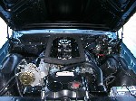
After you remove the pad. There is a series of Phillips screws all the around the perimeter of the bezel. They all point threads up towards the sky. So you need to lay down on the carpet looking up. Also in behind the gauge housing attached right beside the speedometer cable you should find this bracket. If someone has been in there before it my not even be there. It is often left out as it's kind of a pain in the b**t to get back on. It serves 2 functions, a support for the housing and B it's a ground strap. Kind of an important piece.
It connects the backside of the metal gauge housing to the heavy gauge steel bracket which the column is bolted to. Hence the need to lower the steering column. It is not easy to access and you can't see it from underneath the dash. Also understand, you need to remove the radio and the heater control cables (all 3). And, of course un-plug all the wiring. I would label everything if you don't have a good memory on the wiring part.
__________________
Peter Serio Owner, Precision Pontiac Last edited by Peter Serio; 05-12-2019 at 05:18 PM. Reason: spelling fix. |
|
#5
05-13-2019, 12:01 PM
|
||||
|
||||
|
The padded top vinyl is the first thing that needs to come off and it's the last thing you put back after you are all done. Be VERY careful after 54 years underneath the windshield the vinyl will be VERY brittle. It is held on by 3 or 4 of the chrome plated Phillips screws that go underneath the top rolled edge of the bezel. (The ones that point threads towards the sky.) Also remove your cardboard glovebox inner liner. That is so you can see what you are doing. There are at least 2 & possibly 3 threaded studs with machine nuts on the back of the pad. You have to get in behind the steel painted part of your metal dash to see them. There is one on the far right and I think one on the far left side. They have nuts on the studs. The studs are all welded to the metal structure of the dash pad. For all 1966 A body cars across the top under your windshield GM had 5 or 6 large spring steel metal "clips." These clips slide into large holes in the steel part of the cowl; just behind the defroster duct slots. You have to tug the pad towards you to un-clip these. The clips are suppose to stay on the pad support (underneath). Sometimes they fall off when you are pulling on the pad but most often they will stick in the dash. So much so that I have had many people crack their pad trying to pull it off when the clips are stuck. (They freeze in place after being there for years, not moved.)
__________________
Peter Serio Owner, Precision Pontiac |
|
#6
05-13-2019, 01:02 PM
|
||||
|
||||
|
Thanks to everyone who has contributed so far, the advice and knowledge so willingly shared on this forum is a blessing to those of us with the skill level of the Abominable Snowman. The tip about the steering column was certainly something I would never have come up with myself.
I have all the dash harness removed for replacement and all the heater controls and radio out in conjunction with replacing an early gen Vintage Air system. I can only find one threaded stud/nut, the one on the far right (pax) side. Seems like there should be at least one on the left (driver) side as well, but I will be d---ed if I can find it. There a several holding the GTO emblem and grab rail on, on the right side as well, but seem to have no connection to the pad. I guess it comes down to trying to overcome those spring steel clips, don't look forward to how that is going to come out.
__________________
Fort Worth/Dallas TX area 1966 GTO Fontaine Blue 389 CID Carter AFB Muncie 4 speed (orginally an automatic car) |
|
#7
05-14-2019, 05:07 PM
|
||||
|
||||
|
Well, that the pad is finally out, in one piece no less. For anyone's future reference, this pad had only the one stud on the far right (pax) side. I looked at our host's catalog for a replacement pad (just in case, you understand) and in their description they say the repop has two studs, meaning you have to drill a hole on the left (dr) side. Even found the missing spring clip from the previous owner's work, resting in the instrument cluster.
Now that everything is apart (only broke one, wiper, switch), I guess I will bite the bullet on a new dash insert since this one is just a little tired looking. Thanks again for all the advice, couldn't have been at this point without it Mike Pearson
__________________
Fort Worth/Dallas TX area 1966 GTO Fontaine Blue 389 CID Carter AFB Muncie 4 speed (orginally an automatic car) |
|
#8
05-15-2019, 08:09 AM
|
|||
|
|||
|
You are correct about the dash pad from our host, I had to drill the hole in the driver side. It went on easy and looks great, I did the walnut dash insert when I installed Vintage Air as well and it made a huge difference for me on the inside.
Did I see your car at Cars and Coffee Dallas a few years ago? Used to go when I had Corvettes but have not been there with the GTO yet. Randy |
|
#9
05-16-2019, 12:23 PM
|
||||
|
||||
|
Randy, thanks for the info on the dash insert, I am looking hard at that.
I wish it could of been my car you saw, but unfortunately mine has been confined to storage or my garage addition since 2009.
__________________
Fort Worth/Dallas TX area 1966 GTO Fontaine Blue 389 CID Carter AFB Muncie 4 speed (orginally an automatic car) |
|
#10
10-22-2022, 04:49 PM
|
||||
|
||||
|
Following up to this thread since it seemed to be what people might search for: I created a list of steps (in order) that I followed to remove/repair/reinstall my 65 GTO instrument cluster, with a lot of additions. so maybe someone checking on how to add optional switches or wiring can see where it works in the sequence of steps.
Hope this is useful to someone, it helped me keep on track and not do things out of order (like if you go ahead and install the glovebox, you can't get to the pal nuts for the dash pad install!).
Last edited by tallrandyb; 10-22-2022 at 04:55 PM. |
| Reply |
|
|
The PY Online Forums is the largest online gathering of Pontiac enthusiasts anywhere in the world. Founded in 1991, it was also the first online forum for people to gather and talk about their Pontiacs. Since then, it has become the mecca of Pontiac technical data and knowledge that no other place can surpass.


 Linear Mode

