


| FAQ |
| Members List |
| Social Groups |
| Calendar |
| Search |
| Today's Posts |
|
#1
 12-17-2009, 05:16 PM
|
||||
|
||||
 Viper T56 6 Speed in a 1966 GTO Install Guide (long, lots of pics!)
Here we have perhaps the saddest site seen in a “performance” car.
 No, it’s not the dirty carpet or the worn pads, it’s the missing pedal! In the little spare time I had between writing 4 stem cell and regenerative medicine research articles, and by way of more then a couple sleepless nights, I’ve been installing a 6 speed manual transmission in a car that, 45 years ago, hit the road with only 2 forward gears to match these 2 lowly pedals. With the science and science writing finally complete and while still in a writing mode, I have compiled a write-up for installing a Viper T56 in an early A-body, in this case a 1966 LeGTO. Sure, a T56 swap has been done before and done quite well. However, there isn’t a good single source online for all the info for us BOP guys to refer to, and for covering some of the little “gotchas” that sneak up in such customizations. The little things often not covered in a brief post can and will turn 2-3 week projects into 2-3 month+ battles while waiting for parts, for oddball customs, and other unexpected events. My swap was testament to this fact! I spent months researching an ideal pile of parts for the swap, yet still gave my UPS guy a workout sending parts back and forth to Summit, and waiting weeks for backordered pieces I couldn’t have anticipated… By the request of a few friends here also wanting to perform a T56 swap, I’ve made this write up lengthy and detailed as to include many steps to hopefully help more people at various stages. I’ve even documented the basic removal of the automatic transmission steps and have included a guide for installing a LT1/LS1 to supplement the full Viper T56 install, as broken down into sections listed in this table of contents: Auto-to-T56 Manual Transmission Swap Table of Contents: A.) Removing the Automatic Transmission B.) Viper T56 Installation ……1 Viper T56 Basics: ……2 Hole in the Floor ……3 Pilot Bushing, Flywheel, Clutch and Bell Housing Install ……4 Cut Down Input Shaft ……5. CSC Modifications ……6. Clutch Master Cylinder ……7. Clutch Master Cylinder and Firewall Plate Modifications ……8. Custom Dowel Pins ……9. Hoisting the T56 Into Place ……10. Custom Cross Member ……11. Drive Shaft Safety Loop ……12. Fluid Fill ……13. Driveline Angles ……14. Trans Tunnel Fabrication and Install ……15. Interior and Shifter Boot Install C.) Tips for Installing an LT1 or LS1 T56 D.) Part Numbers and Prices I initially happened upon a great deal on a low mileage 1997 LT1 T-56, then quickly sold it in favor of a 2006 Viper T56 with just over 18k miles on it as the superior platform for my planned build. Where a LT1/LS1 T56 was built to handle the ~300HP of the child-seat-ready F-body’s power, the 3rd gen SRT-10 Viper T56 is built to hold the 505 cubes, 510+HP/535+ft/lbs Viper V10 in a max effort, purpose built race vehicle. The Viper T56 is built to handle the 0-60 in 3.5s and a standing quarter in 11.5s at 124mph in a automobile that can pull 1.05G on a skip pad, all numbers I aspire to approach with my own car. This is a trans worthy of a big cube Pontiac engine. Before someone asks, I was tempted to go with an aftermarket T56 or an uber nice new TR6060, or even a TKO600, although the price for those transmissions alone are more then what I paid for every part of my swap, from the trans to new flywheel to custom driveshaft. The Viper take-out conversion made more sense to me. In all, after selling my original trans setup and other original parts, I was able to put the Viper T56 in my car for $980 (breakdown later). Here are a few shots of the noble beast I’m currently working on, a 1966 Pontiac GTO clone. This build is primarily aimed at making the car comparable to modern sports cars in comfort, safety and performance, while retaining the classic style and aura.       With no further ado: |
|
#2
12-17-2009, 05:18 PM
|
||||
|
||||
|
A.) Removing the Automatic Transmission
A.) Removing the Automatic Transmission
To begin with, minding the basics, place the transmission in neutral and remove the front seats, carpet, console and shifter from the interior, chock the wheels and disconnect the battery.  Under the hood, remove the vacuum lines for the trans vacuum modulator and plug the hole in the carb or intake that was feeding the line.  Next, crack open and drain the trans cooler lines at the radiator. Running a Griffin aluminum universal radiator, I had an external cooler on my car so I removed it as shown for draining:   With the car still on the ground, remove the top two trans-to-engine mounting bolts. These bolts are a whole lot easier to reach with the car on the ground vs. on your toes when the car is on jacks.  Now, jack up the car (I like using the engine x-member) and place jacks under the frame (I like keeping the jack in place along with stands for extra safety). Again make sure you rear wheels are chocked and/or the e-brake is on.  You can now easily remove the trans cooler lines and toss them.   Now you can disconnect any kickdown wiring or cables. My car had 2 wires to pull, one for the kickdown, one for the switch pitch pump solenoid.  Disconnect the speedometer cable and shifter cable. 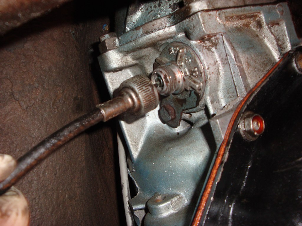  And remove the driveshaft. Have a drain pan to catch the trans fluid that will likely pour out of the tailshaft. I keep a spare yoke to plug the trans for such occasions…   Remove the 3 flywheel-to-torque converter bolts and gently slide the converter into the transmission. You’re now just about ready to drop the transmission. Place a jack under the trans with a large piece of wood (a 2x8, or what have you) for support, jack up the trans a hair, and remove the 2 bolts for the cross member mount, then unbolt and remove the crossmember. You may need to drop the exhaust to remove the x-member if you have an exhaust crossover (I did). Finally, you can remove the remaining 4 trans-to-ending bolts, give the trans a little nudge to free it from the dowel pins, and gently lower it with the jack. Viola, out with the old…  At this point you can now remove the flexplate. Wedging a screwdriver into the holes makes removal a snap.  Here’s what you really want to see at this point at the back of your crankshaft. This crank is drilled for a pilot bearing, as seen in the middle groove with the scored ridge. Not all Pontiac (or other make) crankshafts are drilled for a pilot bushing/bearing. If your crank isn’t cut a custom made bushing or drilling of the crank will be required to install any manual trans. 
|
|
#3
12-17-2009, 05:20 PM
|
||||
|
||||
|
B.) Viper T56 Installation
B.) Viper T56 Installation
1. Viper T56 Basics: Here is the Viper T56 below with a 0.700” spacer attached up front.      You’ll notice a much beefier and longer CSC up front, where the engineers brilliantly put the bleeder outside the case so you can actually get to the valve. The F-body T56 bleeder valve is buried in the case, needing 12 swivel sockets and a double joints in arm and hands to get to. Also notice the thicker/more heavy duty and 0.750” longer input shaft up front and the larger output shaft and 1350 style yoke in back. The Viper unit has a unique tail housing and shifter location relative to the F-body T56. The Viper shifter design is shared with the 2003-2004 Mustang Cobra, giving many shifter options to play with. The factory x-member mount shown is a polyU bushing, and is exactly identical to the TH400 x-member mount bushing, so you can reuse your original mount or one that comes with the trans, if so equipped. The TH400 trans mount fits the F-body T56 perfectly as well, as shown below, although the OEM F-body mount is quite different and won’t directly work with the old GM x-members. 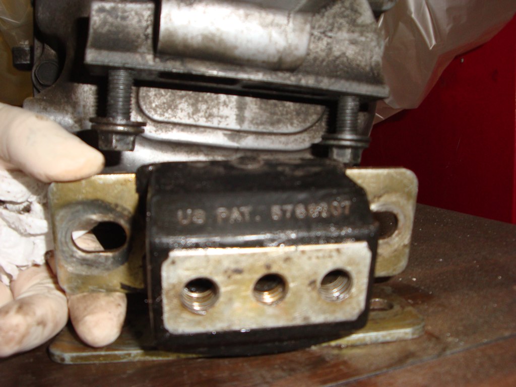 As for the electrical connectors seen on the trans, on the drivers side of the case you’ll see the large reverse lockout solenoid by the shifter hole, and the skip shift solenoid by the top inspection cover. I cut the skip shift solenoid down to the hex nub only and filled it with epoxy to seal it off. The solenoid is in the way of the floor pans and serves no purpose in a 66 GTO. Jumping ahead, I’ve elected to leave the reverse lockout in place but not wired up, as it can be pushed through with just a bit of muscle. Removing the solenoid completely is a no-no, as it has a spring in it required to keep you out of the rev gate when shifting 4-5, that is, unless you think you’d enjoy shifting into R on a 100mph+ 4-5 shift! On the passengers side of the case is the wiring for the reverse lights. There is no neutral safety switch (NSS) or speedo connection on this case. NSS can be wired at the clutch pedal if desired, and speedo signal will come from a simple and inexpensive magnetic pickup to feed a set of custom electrical gauges. The 1st and second gen Viper T56’s have speedo connections, either mechanical or VSS, the 3rd and 4th gen do not. Just FYI! There is some good generic T56 data here, though note this info is generic and most only applies to a LT1/LS1 T56 with a chevy clutch, etc. http://www.pro-touring.com/forum/showthread.php?t=22621 2. Hole in the Floor No beating around the bush, you need to cut a BFHole in your floor to fit the massive T56 in an A-body. You might get away with a slit up to rather then removing the whole tunnel, although I found having the tunnel removed an absolute delight, making work on the car 1,000X easier and making the actual trans install a snap, as you’ll see shortly. A saw-zall, cutoff wheel or, should you be so lucky, a plasma cutter makes quick work of the floor pan. Make sure there is nothing under the tunnel while you are cutting away!: 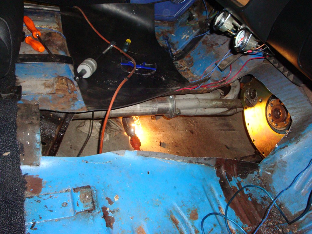 3. Pilot Bushing, Flywheel, Clutch and Bell Housing Install To begin the manual trans install, first order of business is the pilot bearing or bushing. Unlike lesser GM brethren, Pontiac used a pilot bearing rather then bushing in its V8 engines. After much searching, I couldn’t find a custom bearing to fit the viper pilot shaft and the Pontiac crank ID, so made my own bushing from a factory brass piece. I took the common brass bearing sold for the Pontiac, and drilled out the ID of the bearing on my drill press to 0.750”. The ¾” is conveniently the diameter of the Viper input shaft front nub, and also the last size on a #3 stepped drill bit, making cutting the soft brass extra easy. Here is the original RAM (BU75) bushing for the Pontiac V8 (lower left) next to the bushing McLeod sells and said would work (upper right), which was completely the wrong size in every possible way:  I should mention that I custom made my own alignment tool, as the tool supplied with the clutch is for the smaller diameter input (perfect for a LS1/LT1 T56), and a Viper guide tool isn’t exactly a common part at your local autozone, or even easily found anywhere online, for that matter. To make the pilot tool work, my local hardware store happened to have a brass bushing with a 0.750” OD . I drilled out the center of this bushing to tightly slide over the original pilot tool nose, which now perfectly fit the larger bushing and of course properly engaged the clutch disc splines. Here are the mods to the stock size bushing and the custom guide tool:     Here’s a pic with the custom bushing installed:  Next up is installing the McLeod block plate. Easy enough, right? Uh, no…The factory dowels are too short to properly hold and center both the block plate and the new bell, so longer dowels are needed as seen:  Pontiac dowel pins rarely come out without a fight. This dowel was a royal PITA to remove, breaking off a drill bit, not responding to vice grips, ultimately requiring a slit cut into it with an angle grinder for a pry bar and lots of carefully timed cursing to wedge it out.  Here are the longer dowel pins needed for the McLeod bell. They tap right in.  With the block plate installed, the next step is to install and torque on the flywheel to 95ftlbs, installed with loctite and bolts torqued in stages in a star/cross pattern to evenly clamp the plate down. The flywheel only install in one direction, as the mounting hole are “keyed”:  Next up the flywheel and pressure plate are installed. Wipe down the flywheel, clutch disk and PP with mineral spirits or the like to clean every last trace of great and dirt off. This is crucial, don’t skip this step! The flywheel bolts are particular to the Pontiac flyweel/clutch. I used these:  The pressure plate bolts also need to be precisely torque’d in stages to 35 ft lbs in a triangular/criss-cross pattern, as described in the instruction sheet.  Now the bell housing can finally bolt on. A piece of advice: Don’t attach all the block plate bolts until you’re ready to drive the car out of your garage, as reaching, tightening and loosening all the bolts is a real nightmare!  
|
|
#4
12-17-2009, 05:22 PM
|
||||
|
||||
|
B.) Viper T56 Installation
4. Cut Down Input Shaft
After measuring and re-measuring about a dozen times, I concluded that the input shaft is 0.450” too long, and would ram into the back of the crank at its current length. This is nothing a cutoff wheel can’t fix. The front of the shaft is about 0.600 longer then the LS1 or Muncie input shaft to begin with, that is, much of the extra length of the Viper input is in the tip, so removing a little should do no harm and will in fact help line up the clutch disc splines better. Just cut slow and steady and be sure to neatly chamfer the end to help it slide into the pilot bushing. Before:  After:  5. CSC Modifications Before hoisting the trans into place, the slave needed modifications to work in the actuation system I envisioned. I wanted to use the LS1 clutch master cylinder and mounting bracket I had collected previously. After finding this post: http://www.chevelles.com/forums/showthread.php?t=213889 and after brief correspondence with Jon about his T56/clutch setup going in the beautiful 67 Beaumont (a really cool chevelle/GTO hybrid made for the Canadian market), it was clear that the female quick connect fitting in the viper CSC had to be swapped for the LS1 part. Fortunately I had a donor LS1 slave to pilfer from. This was a 2 minute job, requiring pressing out a retaining pin, popping one fitting out and pushing the new one in (be careful of the small rubber o-ring gasket!). You may have noticed the bright orange quick connect fitting in the prior pics. That is the LS1 fitting. The Viper fitting is black, slightly longer and slightly larger. I should note that t this point I also bled the CSC. Using a 50cc syringe to push fluid into the quick connect hole with the connection out made the job easy. Just open the bleeder and slowly pump fresh brake fluid into the slave while keeping the bleeder pointed up. 6. Clutch Master Cylinder Clutch modifications don’t stop there. Here’s where the fun starts. Through trial and error I determined that the factory ~1” travel of the 2002 LS1 clutch MC was a hair too short to fully actuate the McLeod pressure plate and thus fully release the clutch. To get a little more travel I opened up the clutch MC, which is easy work with a small pick under then retaining ring, and proceeded to cut about ½” off the internal travel stop. This step netted a solid 1.5” of total travel and ample travel to release the clutch.    Here is the original excellent write-up on this modification, for where the credit is due: http://www.ls1tech.com/forums/manual...r-writeup.html I was going to perform the “drill mod” on the MC braided line, but found it wasn’t needed on this 2002 line. In way more detail then most will need, the “drill mod” is described here for those that may need it (just scroll to the end for the relevant info with a drill bit in the line): http://www.installuniversity.com/ins...r_cylinder.htm 7. Clutch Master Cylinder Firewall Plate Modifications The aftermarket has provided us with an adapter plate for mounting LS1 hydraulics to vintage Camaros, Chevelles, etc for a few years now.  This bracket doesn’t fit worth a darn in my 66 and required extensive modification to work. Others have informed me that the bracket doesn’t fit well in other vehicles, either. In retrospect I should have just made my own, or even used a Tilton slave, though I stuck with my wet and rusted guns and modified the crap out of this little bracket to make it work. In all the bracket need the booster hole opened way up to fit my hydroboost setup, the angle needed tweaking to align the rod with the clutch pedal, the MC mounting pad needed trimmed slightly to fit the bend in the bracket and the mounting bolt holes for the MC needed opened up 2 sizes. I welded bolts to the bracket for the MC to make install/removal a ton easier. The bracket is really hard steel, and grinding and drilling on it was a b!^(h.      It took a lot of time to tweak this part. Here is the final version of the clutch MC on the modified plate, with high density foam to seal the clutch rod hole in the firewall and a new MC. I obtained used clutch MC and CSCs from friends to do the mockups and used new parts for the final install. Since I here had the bracket, master and slave figure out I bench bled the clutch MC extensively. With fresh brake fluid, using a simple gravity bleed method followed by slow pumping and inverting of the MC to let air bubble escape up into the rez. To know when you are done bleeding, the rod effort will go from nothing to very hard and upon pumping or inverting the MC no air will escape. Gently tapping the MC also helps free up air bubbles.  Here is a shot of the installed reservoir, plate and MC, the latter of which can not easily be seen as they are well buried under the hydroboost unit:  I originally made the MC actuator rod adjustable by threading it and installing an eyelet, though later found it much better to leave the rod alone and just drill a new hole in the clutch pedal for mounting the MC rod, which is easy enough to do. Here’s the current pedal/clutch MC setup, which may change in the future:   As a side note, I’m using 1967 brake clutch pedals in my 66. By dumb luck, these gave me a better alignment for the hydroboost push rod vs the 66 brake pedal. The 67 clutch pedal mounting tab is well place for the hydraulic clutch MC, although it does require slight modifications to fit the 66. Here is another pic of the clutch pedal with the temporary pedal stop I mounted to the floor, made from what was once a 1998 Jeep TJ tire carrier bumper:  8. Custom Dowel Pins As I am using the McLeod scalloped spacer ring I needed a set of dowels to run from the bellhousing into the spacer. Not one machine shop, parts store or hardware store in all of Richmond carried a simple 3/8” dowel pin, much to my surprise. Not wanting to be sitting around waiting a week for yet another mail order part, I decided to make dowels myself by cutting down a 3/8” drill bit to the appropriate length and chamfering the edges, as seen here with one tapped into place in the bell.  9. Hoisting the T56 Into Place A few emails back and forth with Vic, alias 6D6GOAT on PY, convinced me to cut a larger rather then smaller hole in the trans tunnel to fit the T56, and I’m really glad that I did. Vic posted an excellent T56 conversion write-up in his gorgeous 1966 GTO convert here: http://forums.maxperformanceinc.com/...eed+conversion The reasons for a nice big hole are many. The T56 again is quite large, and if you cut too small it will be harder to use the cutout section as the basis of the later patch, for one. Secondly it’s a joy reaching through the hole for parts or tools rather then having to get from under the car to reach them. Thirdly, bleeding the cluch MC from the cabin is a joy. Lastly, installing the 135lb transmission with a cherry picker beats the heck out of fumbling and grunting on the ground with a trans jack or, worse, bench pressing the trans into place like I’ve done in my younger if not dumber days!   Using extra long bolts to get the trans and bell aligned makes bolting the trans up and hitting the pilot a snap. Make sure the T56 is in neutral and connect the clutch MC quick connect to the CSC quick connect before fully bolting the trans to the bell to prevent damaging the pressure plate. Here is a shot of the CSC in the bell with the trans fully bolted up. Notice there is about 0.400” left for the slave to compress before binding, with is plenty or room to compensate for the pressure plate fingers moving out a bit due to centrifugal force while spinning, and to accommodate for clutch disc wear. The Viper CSC has 1.5” of total travel, so with about 1” of travel left there is more then enough room to engage the clutch, as the McLeod pressure plate only required 0.450” of travel to operate (though should not exceed 0.650 or so, according to the McLeod techs) 
|
|
#5
12-17-2009, 05:23 PM
|
||||
|
||||
|
B.) Viper T56 Installation
10. Custom Cross Member
Next up is to modify the factory trans cross-member for the ~1” lower sitting T56 trans mount. With the trans supported by a stand I dropped the exhaust to get the cross member in and out more easily.  It’s really nice sharing a warehouse with a couple of fellow car guys, as between us we have a ton a great tools to play with, from heavy duty cutoff saws, to MIGs and TIGs and a great set of air tools to make jobs such as this easy. To start with I used the saw to make 2 cuts on the flattest sections of the x-member by the mounting hole. I then went in with a cutting wheel to remove the mount section, leaving the back of the x-member intact to retain the straightness, length and alignment of the x-member as much as possible (cutting out the whole section in 2 cuts would have made the job harder for me)    Next I cut 2 rectangular pieces of thick steel to weld into the sides of the sectioned hole, and then, after careful measurements and checking the height with the plate just spot welded in, I welded the mounting plate back in for good. Miraculously, the x-member fit beautifully and the rearmost two x-member mounting holes on the frame lined up perfectly with the new mounting location!    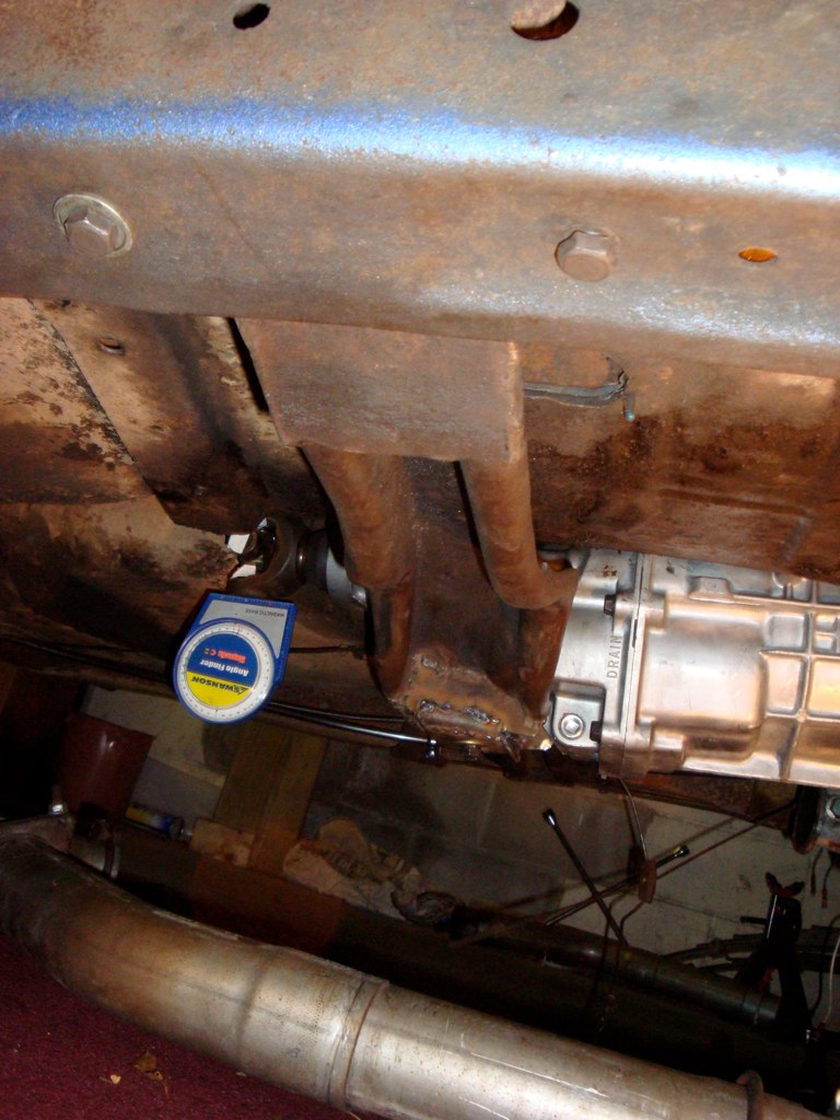  11. Drive Shaft Safety Loop A driveshaft loop is a given on a such a buildup, required for racing and is simply a good idea for spirited street driving as well. In typical universal part fashion, the universal driveshaft loop from Summit is a truly one-size-fits-none piece. Here are the before, after and—after a lot more work then there should have been—the installed pics of the loop.    12. Fluid Fill Next up was to install the billet shifter and fill the trans with fluid. The shifter is an UPR Blue Thunder model with spring assisted 2-3, shift stops and a fairly nice lever and knob included that will tide me over until I finish my custom console with a new shifter stick and knob arrangment. The shifter seals to the case with a very small bead of RTV, and the stops must be set carefully per the instructions. I filled the trans through the inspection cover with the required 3.8 quarts of fluid. NOTE!: on this Viper T56 and all later model T56 transmission, only Castrol Syntorq is approved for use. Amsoil recently released the shown API GL4 75w90 fluid for the Viper T56, which is half the price of the stealership-only Castrol Syntorq (same as GM Synchromesh). Having a friend who is the local Amsiol dealer made my fluid choice easy. Do NOT use ATF in this trans! Only the old LT1/LS1 T56’s can take AFT, ONLY!:      13. Driveline Angles The final critical mechanical parameter left is setting up the pinion angle so the custom HD driveshaft, now spinning at insane speeds in its 0.5 overdrive with 4.56 rear gears, lives a long happy life. The angles must be measured with the weight of the vehicle on its suspension. You can get a good measurement of the rear angle from the flat portion of the yoke, and get a good reading from the trans at the flat across the rear seal, or even use the block oil pan rail for a good measurement, triangulated off the front balancer pulley, or the u-joint cap in the yoke, among other places. Once you find your angles, setting them up equal and opposite is easily done with adjustable rear control arms, such as the nice UMI Performance arms I’m using.    I set the trans up as high as it would reasonably fit to begin with and it was sitting 6deg down. The differential was sitting 4 deg up so it needed to go up 2 degrees to match. This is a very basic write up here that doesn’t do the subject justice. For a more complete guide for setting up the angles check out these great articles here: http://www.classicchevy5speed.com/fi...roc_111606.pdf http://prostreetcamaro.com/dshaft.shtml |
|
#6
12-17-2009, 05:24 PM
|
||||
|
||||
|
B.) Viper T56 Installation
14. Trans Tunnel Fabrication and Install
Fabricating a new trans tunnel is the final bit of customization. Working with a piece of sheet metal as thick as the factory floor pan, I used the original floor section as the foundation for the new cover. I started with simply cutting long 3” wide sections to add to the original tunnel, then welded on a new flat section around the shifter. The shot here is prior to 2 hrs of hammer and dolly work to blend the lines with the original and tighten up the cover. After getting the new tunnel tacked in place I covered the entire patch with a few layers of self-adhesive sound deadener to both seal any leaks and keep the noise of the trans down as much as possible. I have a second sound deadener large sheet to top the entire floor pans that goes between the carpet as well.     If you’re looking for info on sound deadeners, you must read this test before buying anything: http://www.sounddeadenershowdown.com/sds_old_site.pdf 15. Interior and Shifter Boot Install Finishing things off, only re-installing the interior with a new shifter boot remains. I’m in the process of fab’ing a console for the car using leather matched to the 2006 GTO seats. The boot on the floor is just temporary but I think it looks nice as is, too, and is far cheaper then a nice original console. For what it’s worth, however, I think a factory auto console would fit perfectly here, though I’d hesitate to use one given the cost for nice specimen. A manual trans console could work too, though the placement of the shifter is better set for the auto consoles. Here’s a pic of the boot used and the interior shots:   
|
|
#7
12-17-2009, 05:25 PM
|
||||
|
||||
|
C. Tips for Installing an LT1 or LS1 T56
C. Tips for Installing an LT1 or LS1 T56
  While I ultimately used a Viper T56, I initially started my T56 swap with a 1997 Camaro LT1 T56, which taught me a few things that you might find useful. For reference, here we have a LS1 bell (left), McLeod Modular bellhousing (8710-00) and an LT1 bell (right). You’ll notice they have the same depth and very similar mounting holes on both sides.    The LS1 and LT1 bell can mate a chevy engine directly. A common BOP-Chevy adapter can be used to bolt one of these to your Pontiac (http://www.summitracing.com/parts/TRD-0061/?image=large) to mate the T56 to a Pontiac engine. This is the route I initially though I’d take, with the LS1 bell and adapter. After realizing the LS1 bell is worth $200+ (sold it for $220), and add $100 for the adapter, plus $50 for the custom 0.500” thicker pilot bushing, the bomb proof McLeod Modular bell with a block plate at $425 made a ton more sense on many levels (direct from McLeod I actually got the bell at $325). A stock LT1 T56 is the least ideal T56 for a Pontiac, as the input shaft is far too short. As you can see here the input shaft doesn’t get anywhere near the pilot hole, which, conveniently for reference, happens to be about dead center of where the block plate aligns.  LT1 input shaft coming up short:  Whereas the LS1 shaft input shaft is about perfect in length:   Here I’ve also illustrated the length difference by placing the shorter LT1 and longer LS1 shaft next to each other:   A LT1 T56 can however easily be modified with a longer LS1 or Viper input shaft, which can be swapped alone or along with the front plate for the LS1 or Viper T56. Here we have the LT1 T56 with the front plate removed. Removing the front plate and input is a simple process. Just remove the bolts on the front plate, pop the plate off and gently pull the shaft out while twisting (sounds dirty, I know ☺ ).  Here I have the LT1 and LS1 front plate and input shafts next to each other so you can clearly see the difference in input shaft height, and the difference in the plate to help easily ID the different versions. The LT1 is designed to have a traditional mechanical throwout bearing (TOB) and fork installed on the plate (not shown), and thus sports a bearing retainer. The LS1 front plate has a machined surface to accept a hydraulic throwout, or more precisely a concentric slave cylinder (CSC).  Installing a new shaft and/or front plate on a T56, is not as easy as removing the original, as you must set the shaft/plate spacing with small spacer shims, as described in the T56 manual linked to here: http://www.ttcautomotive.com/English...ice_Manual.pdf Here you see the bearing race removed from the front plate with a thin shim that goes underneath to properly space the input shaft:  While I had the LS1 front plate and input off I did some mock ups to see how it all would fit with the clutch and bell installed in the car. While the spacing for the shaft and pilot is good, unfortunately the factory LS1 CSC is too big to fit in the small bellhousing space without binding, effectively leaving the clutch partially engaged at all times, as shown:  Not a good thing. RAM offers a universal CSC that might work (http://www.summitracing.com/parts/RA...5/?image=large), though the thought of a hard to find and expensive CSC is not appealing. A McLeod scalloped (8703-13) spacer would be needed to make room for the F-body CSC, or you’d need to find a different TOB setup, perhaps even going with a mechanical TOB setup by using a plate such as this (http://www.summitracing.com/parts/MC...7/?image=large) Problem here with the mechanical TOB plate adapter, or the McLeod spacer, is by putting the trans 0.500-0.700” back to fit the TOB, your input shaft is now too short to fully engage the Pilot bearing/bushing, and a custom made bushing is required (and/or use of the longer Viper input shaft). McLeod lists in their catalog a custom extended pilot bushing for Pontiacs just for this very situation, part number 8-1380-1. However, this part is completely wrong, and neither the bushing ID or OD is correct for a Pontiac/Olds crank or any T56 input, respectively. You’d need to have a bushing custom made to make this setup work, which is not a big deal for your local machinist, or perhaps call McLeod to get the proper part number, as they claim in their catalog to make such a bushing. Thus, the LS1 T56 is a completely workable solution, with just a few different twists to address. At this point I switched gears to make the Viper T56 work in my Poncho, so have nothing more to share here, although the basic install from here on would largely mirror the steps listed for the Viper trans... |
|
#8
12-17-2009, 05:26 PM
|
||||
|
||||
|
D.) Part Numbers and Prices
D.) Part Numbers and Prices
In the end I spent $980 to get the T56 in the car after selling off the original auto and associated spare parts. I’m not saying this is a fair or representative amount of money for this conversion; it’s just what I paid. I sold my existing very nice switch pitch/trans and associated parts for $1400. I sold my 12 bolt posi with 3.31’s for $900 and purchased another rebuilt 12 bolt Posi with 4.56’s for $450 from a friend. I offset all of these costs listed below quite a bit by selling my old parts and also by selling off hundreds of dollars worth from the spare parts I didn’t need that came with some of what I bought for the swap, such as the OEM viper shifter and driveshaft, the 66/67 GTO driveshaft, etc. The swap could have been done cheaper, and it could have been done for a lot more, all depending on what parts you choose, and particularly based on which T56 you wish to use and how patient you are for a deal. Unless otherwise noted, part numbers and prices refer to the Summit Racing catalog. -2006 Viper T56 Take-Out with Shifter, Mount, Elec. Fittings & Yoke ($1200) -Amsoil SLI G4 75w90 Synthetic Fluid ($35 for 4 quart, local dealer) -ARP Pressure Plate Bolts # ARP-190-2210 ($12.25) -Clutch/Brake pedal, 1967 GTO take-offs ($45, ebay) -Clutch Master Firewall Bracket ($35, ebay, or $85 via ATS) -Driveshaft, 3.5” mild steel, balanced to 10,000RPMs ($250, local HD truck shop) -Hays Neutral Balanced Steel Flywheel # HYS-13-130 ($265) -Lokar Shifter Boot and Trim Ring # LOK-70-FMB ($31.95) -McLeod Modular Bellhousing # MCL-8710-00 ($424.69, $325 direct via ebay ) -McLeod Scalloped Spacer # MCL-8703-13 ($184.99, $50 used via ebay) -McLeod Super Street Pro Clutch Kit # MCL-75221 ($324.99) -Moroso Extended Block Dowel Pins # MOR-37932 ($10.25) -Perfection Clutch Master Cylinder, 2002 LS1, #PFC-250125 ($71.99, Advance Auto) -Ram Brass Pilot Bushing # RAM-BU75 ($5.95) -Sound Deadener and Floor Sealer, 25ft roll ($15, Home Depot) -Summit Driveshaft Safety Loop # SUM-G7900 ($24.95) -UPR Blu Tunder Shifter, Stick & Knob # UPR-3002-03 ($149.99, $65 direct via ebay) Last but not least I’d like to thank Andrew Borodin (Andrewb70), Jack Blum, John (JC455), John Farrugia, Tod Hoffman (6Grrrs) and Vic Shockley (6D6GOAT) for the help and suggestions offered for getting this project done. They’ve all journeyed down similar roads before and had great suggestions to offer along the way. Swapping in the 2006 Dodge Viper T56 into my 66 GTO has been the most fun I’ve had working on a car in many years. It is not a terribly difficult swap, though there are many little challenges with numerous opportunities to put your creativity and fabrication skills into the process. I’ve posted the most germane images of the conversion in this thread, and my flickr account has a few hundred additional pics I snapped along the way that you might find entertaining or useful, or utter garbage, so feel free to peruse the related folders if you desire supplemental images. If anything needs clarification or if you have any general questions I’m happy to help where I can! Last edited by Socrates; 12-17-2009 at 05:36 PM. |
|
#9
12-18-2009, 04:18 PM
|
|||
|
|||
|
Awesome job, dude!
I recognize some of the tech links... great write up!
__________________
John IG: @crawdaddycustoms YouTube: https://www.youtube.com/channel/UCK9...Nc_lk1Q/videos |
|
#10
12-18-2009, 04:53 PM
|
||||
|
||||
|
Wow, nice write up
I really like the picture of the engine hoist holding up the tranny inside the car. haha that is awesome
__________________
Robert Lewis 1959 Star Chief 4 Dr HT dual quad 389 4 speed 1962 Pontiac Plain Jane Catalina http://pontiac-59.com/ |
|
#11
12-18-2009, 08:52 PM
|
||||
|
||||
|
This write up is worthy of a sticky I reckon.... that's fantastic!
|
|
#12
12-18-2009, 10:08 PM
|
||||
|
||||
|
Nice work...and what a great post....I mean you even put a picture of the battery disconnected.
 I second the sticky motion. I second the sticky motion.
__________________
Vic in SoCal. Follow me on Instagram- Cloud9orbust 66 GTO clone, 467 cubic inches of Turbocharged Multiport Fuel Injected fury twisting a TH400 into 3.90's wrapped in a 12 bolt posi.  My T56 Install My Turbo Build My Vortech Supercharger Build Hyd Throw out bearing Misc Build Pics May the Karma Gods meet you half way.... |
|
#13
12-21-2009, 12:04 PM
|
||||
|
||||
|
Glad ya'll enjoyed it. Hoisting the trans up with a cherry picker through the center of this car was a trip! I had a big stupid grin on my face the entire time. I got the idea from the auto-to-manual swap I did on my Scout II, which has a removable plate for the trans tunnel factory. My trans floor jack was useless with the ~250lb T-19/bell and I had to use the engine hoist to lift that dump truck trans (literally) into place the same way!
|
|
#14
12-21-2009, 12:31 PM
|
||||
|
||||
|
Very Good Info. Would like to know how the .50 overdrive with the 4.56 rear works out?
What RPM does it go down highway at 70MPH? Thanks |
|
#15
12-22-2009, 03:56 PM
|
||||
|
||||
|
Quote:
 ! I wanted 4.11's in the rear, ideally, though couldn't pass up the deal on the fresh 4.56 12 bolt. ! I wanted 4.11's in the rear, ideally, though couldn't pass up the deal on the fresh 4.56 12 bolt.
|
|
#16
12-23-2009, 12:03 PM
|
|||
|
|||
|
Soc, I want to be just like you when I grow up!!! Seriously. I love reading your posts, since way back on CP.
|
|
#17
12-23-2009, 05:47 PM
|
||||
|
||||
|
Wow...holy write up Batman! Lots of great info there.
Question....mounting the new GTO seats...what did you do there? I have some I'm planning to install and since I won't be doing it for a while, what did you have to do to make them fit? Thanks. |
|
#18
12-23-2009, 05:59 PM
|
||||
|
||||
|
Great detailed article. No mag could come close to this. WOW. Now others can use your experience and sharing to make their installation easier. Not easy just easier.
__________________
JLP |
|
#19
12-23-2009, 10:17 PM
|
||||
|
||||
|
Heres another bellhousing option. Pontiac to LS1 T56.
http://www.quicktimeinc.com/products.html#olds
__________________
'73 Formula 400 Cammed LS1/T56/3.73's [email protected] 2.03 60 ft. <~~ Bone stock LS1 with 4L60E/3.08's Went 12's in pure daily driver trim! A/C, leather power seats, power steering, full stereo, sound deadening, power windows, full suspension, true street tires, power 4 wheel discs, and 25MPG! |
|
#20
12-24-2009, 08:31 AM
|
||||
|
||||
|
[quote=Pontiac dowel pins rarely come out without a fight. This dowel was a royal PITA to remove, breaking off a drill bit, not responding to vice grips, ultimately requiring a slit cut into it with an angle grinder for a pry bar and lots of carefully timed cursing to wedge it out.[/quote]
Great info and write up.. Wow.. Here's a tidbit of info that may help someone down the road with these Dam Dowel pins. I went to remove mine last year and one came out easily. The other one would not move. I took a grade 8 bolt, cut the head of it and had my son weld it to the dowel pin. I put about 8 flat washers over it and threaded a nut on it and out it came. You can use ready rod also. Just have plenty of flat washers on hand.. That's it.. Charles
__________________
68 Firebird. IA2 block, 505 cu in, SD Performance E-head, Solid roller 3600 weight. Reid TH400 3:90 gear. 28" slick. Best so far 9.95@135 mph. 1.39 60 ft. 76 Trans am, TKX .81 o/d, 3.73 Moser rearend, 468 with KRE D-ports, Doug headers, 3" Exhaust 950 Quickfuel. |
| Reply |
|
|
The PY Online Forums is the largest online gathering of Pontiac enthusiasts anywhere in the world. Founded in 1991, it was also the first online forum for people to gather and talk about their Pontiacs. Since then, it has become the mecca of Pontiac technical data and knowledge that no other place can surpass.




 Linear Mode

