


| FAQ |
| Members List |
| Social Groups |
| Calendar |
| Search |
| Today's Posts |
|
#1
 06-25-2011, 03:51 PM
|
|||
|
|||
 72 Fender Air Extractors
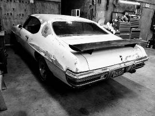
We're getting ready to cut into the fender patches to install air extractors for the '72 GTO. I can't find any diagrams or details on where these things go, so using some photos and measurements from an actual fender we did a little math and came up with the extrator to be mounted...
6.83 " above the bottom of the fender, parallel with the bottom of the fender. 3.56" back from the fender opening (measured at the lower corner of the extractor) 3.56" below the "point" in the fender, the sharp countour in the middle (measured from the upper corner of the extractor) First we'll mock it up in a piece of metal to see if we can cut the hole and flange the metal properly. Then into the actual fender. Will let you know how it comes out. |
|
#2
06-25-2011, 06:06 PM
|
||||
|
||||
|
I'll be able to get that tracing I promised you in a few weeks if you can hold off that long.
IIRC there is a small recessed lip that the extractor sets into so it will fit flush once installed. |
|
#3
06-25-2011, 07:01 PM
|
|||
|
|||
|
I don't know if this helps any, but I bought an 8x10 picture off of ebay, that is the white attachment. I bought some 'scrap' fenders from guys, but ended up buying 3 sets before getting a set that was useable. We cut them into a set of Lemans fenders. I took 3 pictures of one fender. I put a couple of long screws into the factory holes in the wheelwell (for the wheel opening molding screws), use these to help guide your vertical location.
I layed the black ruler parallel to the top of the reveal, and layed a tape measure from vertical as well. The horizontal location is a bit more difficult to measure. Let me know how I can help. Mike |
|
#4
06-25-2011, 10:33 PM
|
|||
|
|||
|
Thanks Mike... your post helps a lot. We made some progress tonight, and with the photos you sent we'll be able to make the adjustments needed to produce an even better final product!
Steve: I appreciate your assistance, and when you get the tracing try to post it up here, I know others will be attempting this in the future (heck, we may be doing it again if we screw these fenders up too badly  ). ).Here's where we're at... Worked the fender extractor placement and installation tonight, however, putting together the prototype was a bit more difficult than we bargained for. My son (he's 15, it's his car!) did the calculations, cut out a paper pattern and placed it on the fender. We pulled the measurements off of this photo of an old crusty fender, using known measurements from the fenders we've got to develop the ratios. For tomorrow's work we'll incorporate the measurements from Mike's post below to refine the placement. Then tried to cut the pattern into some scrap metal. First attempt we attempted to cut the pattern and use a pneumatic flanging tool to give us the step-down that allows the extractor to fit flush. After a lot of cutting, grinding, flanging, grinding, etc... it just didn't fit. The flanging tool didn't make a deep enough "groove"; the flange was just too shallow. We won't be able to exactly duplicate the flange, but will come close using the tab method below. Second attempt is shown in the photos attached. We measured it out, then cut in some tabs to bend back the metal in order to fit the extractor in. It fit fine, with some minor adjustments this process will work well enough. We can rebend the tabs to create the flange the extractor sits in in an original fender. As with most things, we thought we'd have these things in tonight... now we're hoping to get 'em both done tomorrow. Figuring out how to do it is half the battle with us, but we spent some good time designing and running through the numbers to come up with a workable solution. Hope to post some more refined photos tomorrow night! Gonna knock off for tonight and take in some of the Norwalk drag racing on ESPN2! |
|
#5
06-26-2011, 09:22 PM
|
|||
|
|||
|
Got both fenders mocked up, one sorta finished. Here's how the passenger side turned out. Since we can't make the flange deep enough with the flanging tool, the extractor is mounted flush using metal tabs and the mounting hardware on the extractor. The downside is no defining "groove" around the extractor. May be able to fabricate that using some sort of scribe or cutting tool. I'll work that a bit later. Got my son to do most of the work today and I was able to have a cold one and "supervise" !!
Well, actually I had to sand a bunch and clean up! Have a good week, hope for more progress next weekend. Thanks to everyone for the assistance. Dave |
|
#6
07-16-2011, 12:20 AM
|
||||
|
||||
|
WOW!
Lots of fab work right there............. I have those fenders on my 72.
__________________
72 Lemans Sport convt., 84 Z-28, 13 Chevy Impala, 94 Buick, 77 Triumph Bonneville |
| Reply |
|
|
The PY Online Forums is the largest online gathering of Pontiac enthusiasts anywhere in the world. Founded in 1991, it was also the first online forum for people to gather and talk about their Pontiacs. Since then, it has become the mecca of Pontiac technical data and knowledge that no other place can surpass.





 Linear Mode

