


| FAQ |
| Members List |
| Social Groups |
| Calendar |
| Search |
| Today's Posts |
|
#281
 08-02-2009, 12:06 PM
|
|||
|
|||

Bart, are those new 1/2" bolts an interference fit in the frame, or just slide in? I ask because I have the same arms yet to be installed. I currently have the Hotchkis arms in there, too, thus my inquiry.
Thanks.
__________________
How many of you have driven over 340? 
|
|
#282
08-02-2009, 12:46 PM
|
||||
|
||||
|
Quote:
They don't have an interference fit like the factory bolts do with the splined portion just under the bolt head. With the rubber splash shields removed there's easy access to them. I did put some red Loctite under the bolt heads to help keep them in place. Since the SPC arms are fully adjustable you're not supposed to need any alignment shims so once they're tight you can forget about them. Just in case some shims were needed later I left the bolts a little long so a 1/2" tall stack of shims could be used if needed. Bart |
|
#283
08-02-2009, 04:23 PM
|
|||
|
|||
|
Thanks Bart. Next question, where did you get these bolts? From SC&C?
Thank you.
__________________
How many of you have driven over 340?
|
|
#284
08-02-2009, 11:52 PM
|
||||
|
||||
|
Quote:
|
|
#285
08-03-2009, 12:19 AM
|
||||
|
||||
|
Spent my day.....
.....in the garage finishing the front suspension mock-up.
First order of business was to get the SKF racing hubs prepared. For starters, the studs are too long. Since I'm using wheel adapters the studs need to be shortened to match the thickness of the adapters (1.063") plus the thickness of the front brake rotors (.300"). 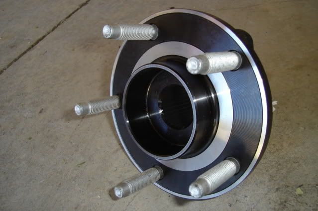 I ended up grinding about .400" off the ends of the studs. 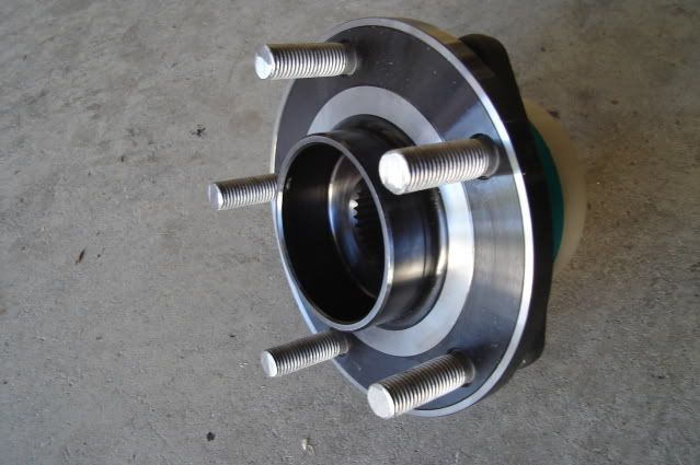 The AFX spindles use two bolts and one stud to mount the hubs. The hubs were designed to use 3 bolts so all three holes are threaded. In order to use the one bottom mounting stud on the AFX spindle I had to drill out the threads in one of the holes with a 1/2" drill bit. 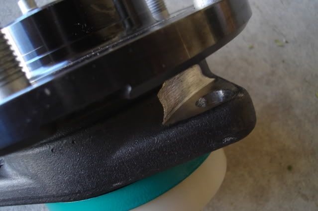 I had to use a die grinder with a cutting wheel to make some clearance for the nut to turn and to provide a flat area for it to tighten down onto. 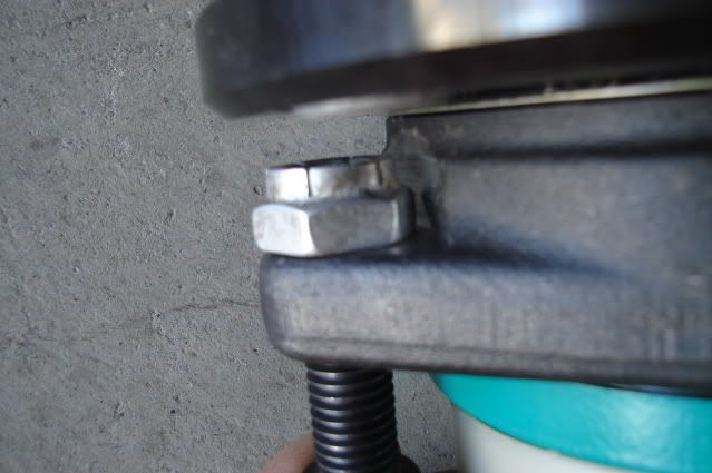 After having a lot of fun hacking on my new hubs they're now bolted in place. 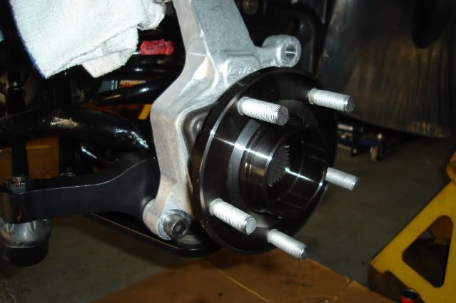 New 14" rotor and wheel adapter mounted up to the hub. The adapter solves two problems, converting the front bolt pattern from 5 on 4.75" (5 on 120.65mm) to 5 on 120mm and effectively reducing the backspacing on the wheel to 5.507" from 6.57". I had to grind about .060" off the ends of the lug nuts holding the adapter in place for clearance. 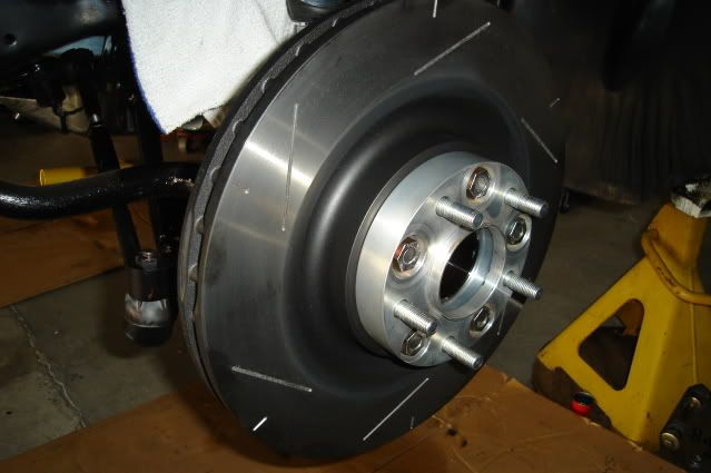 Bolted the wheel in place. No brake calipers yet, not enough time today with all the drilling and grinding going on. 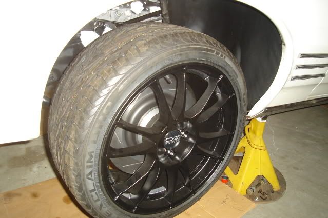 Looks like there's plenty of clearance between the upper A-arm and the inside of the rim with the wheel turned all the way to the left, the clearance here will increase with the car's full weight on the suspension. 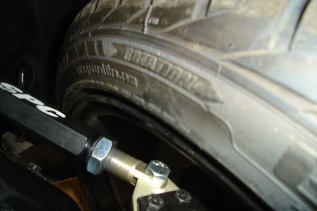 Set the car on the ground to see how it looks. I'm pretty happy with the ride height considering the amount of weight that still needs to be put back in the car. No seats, front or rear glass, most of the exhaust system out, no belt-driven accessories on the engine, no fluids in the engine or trans, no A/C compressor and no hood or right front fender. 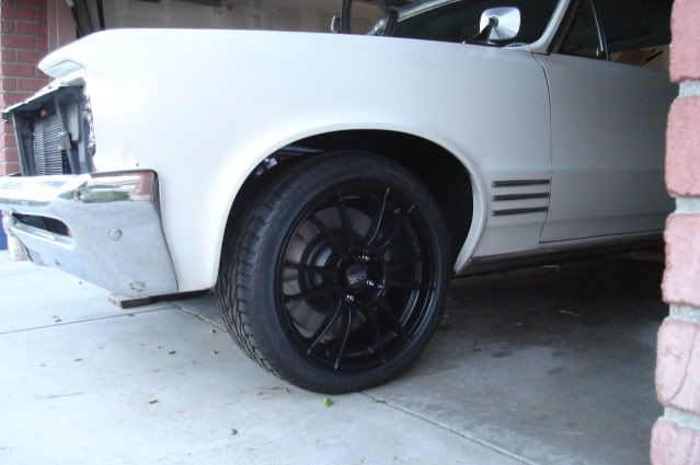 The AFX spindles have 1" of drop built in, combined with the 1" drop from the SPC lower control arms it's looking like I won't need to trim the front springs. 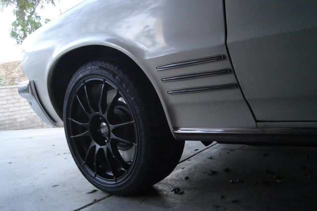 I reached my goal of getting the car sitting back down on the ground on all 4 wheels this weekend. I'm stoked.
|
|
#286
08-03-2009, 09:43 AM
|
||||
|
||||
|
I see that the hubs are splined in the inside. are they designed for a shaft to go through them?
That's some pretty looking stuff you are putting on that car. BTW how far over 'budget' are you so far.  
__________________
North Dakotas fastest REAL GTO 10.10 @ 131 MPH in the 1/4 Hoping to get it back together some year. www.jandjrepairandrestoration |
|
#287
08-03-2009, 06:38 PM
|
||||
|
||||
|
Quote:
I'm about 5K over my first 'hopeful' 12K estimate on the LSX-related swap parts with the aftermarket A/C included. That doesn't account for the 8.5" rear end, suspension and brakes or wheels and tires that I decided to add midstream in the project. These projects tend to snowball on you sometimes. Doing it once and doing it right does cost you, but it also saves you from spending more doing it over when you're not really satisfied with the first outcome. |
|
#288
08-03-2009, 08:48 PM
|
|||
|
|||
|
Quote:
 You are doing a fine job...well done!
__________________
How many of you have driven over 340?
|
|
#289
08-03-2009, 09:43 PM
|
||||
|
||||
|
Quote:
__________________
North Dakotas fastest REAL GTO 10.10 @ 131 MPH in the 1/4 Hoping to get it back together some year. www.jandjrepairandrestoration |
|
#290
08-03-2009, 09:55 PM
|
||||
|
||||
|
Quote:
|
|
#291
08-05-2009, 12:14 AM
|
||||
|
||||
|
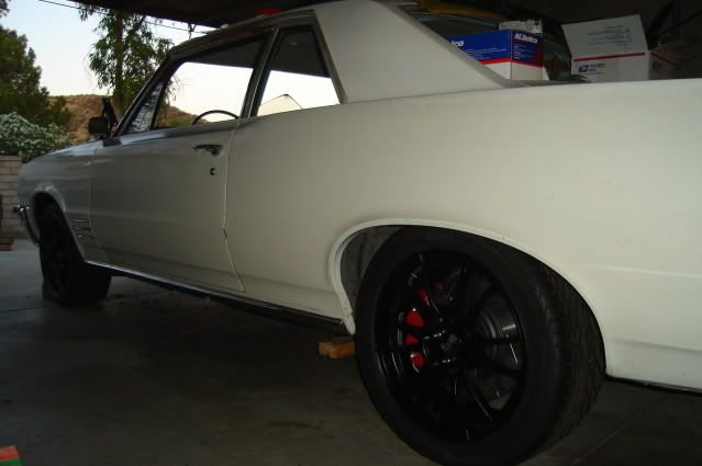
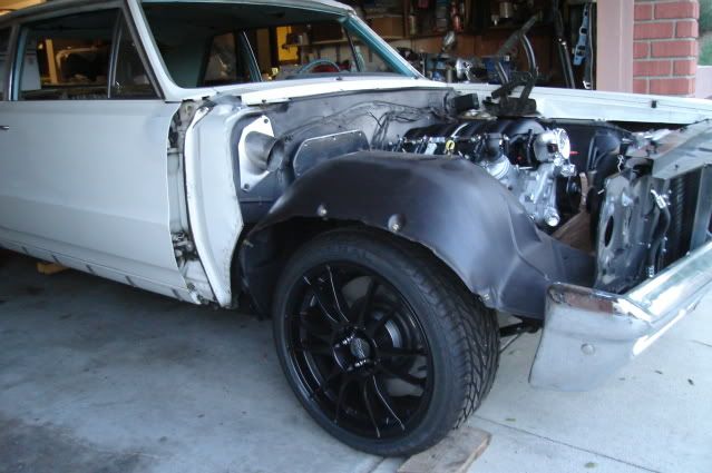
Nothing new happening today,.....
.....just thought I'd post a couple more pics taken on Sunday evening.
|
|
#292
08-05-2009, 02:31 AM
|
||||
|
||||
|
b-man what's that silver snorkel over where the heater blower used to be?
|
|
#293
08-05-2009, 01:15 PM
|
|||
|
|||
|
Bart: Send me your PH#. or gimme a call @ 909-980-1451
__________________
GOOD IDEAS ARE OFTEN FOUND ABANDONED IN THE DUST OF PROCRASTINATION |
|
#294
08-05-2009, 08:52 PM
|
||||
|
||||
|
Quote:
Quote:
Bart |
|
#295
08-08-2009, 09:21 PM
|
||||
|
||||
|
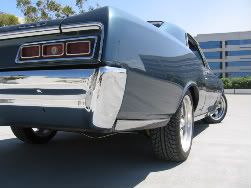
This looks like its going to be awesome! I am really digging those wheels!
__________________
|
|
#296
08-10-2009, 12:34 AM
|
||||
|
||||
|
About to enter.....
.....somewhat unfamiliar territory as it's time for me to start installing the wiring harness and controller.
The engine harness part of it is pretty straight-forward, just match up the connectors and plug them in. Figuring out the best place to mount the bulky ECM is a bit of a challenge, there's pretty much no room under the dash for it with the A/C unit and ducting hoses taking up most of the space on the passenger side. I laid out the harness inside the car to start becoming familiar with it. Everything shown here on the passenger side floor will be on the inside of the firewall. Included is the ECM, pedal harness for the electronic throttle control, fuel pump relay, cruise control wiring, and four 20-amp fuses and power up wires. 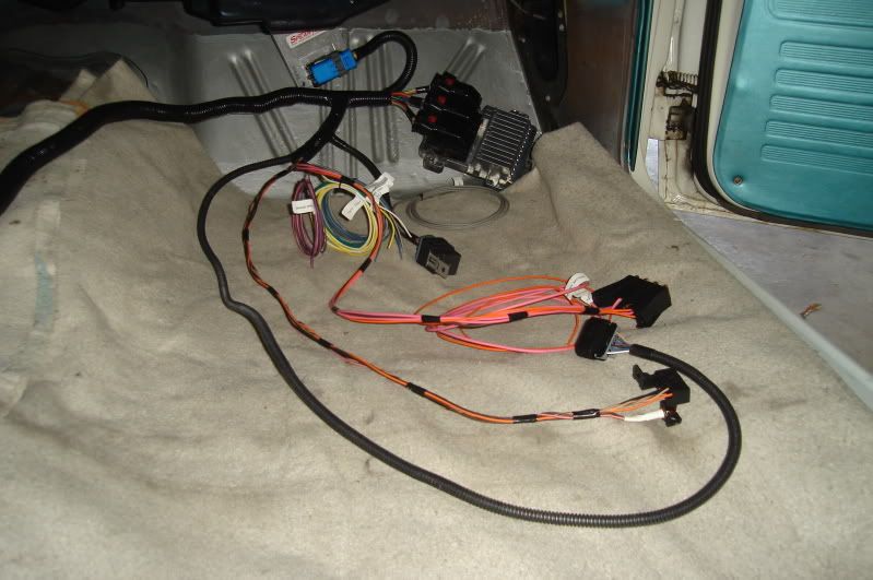 Here on the driver's side the engine harness is laid out. All of the wiring and connectors shown here will have to pass through a 2-1/8" hole in the firewall. Finding a good place to cut that hole is my first task. 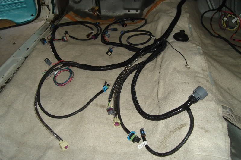 After taking the harness to the engine side of the firewall and plugging it into most of the connectors on the engine and transmission I was able to figure out a good place to run the harness through the firewall. The hole where the throttle cable used to reside looks pretty much ideal. 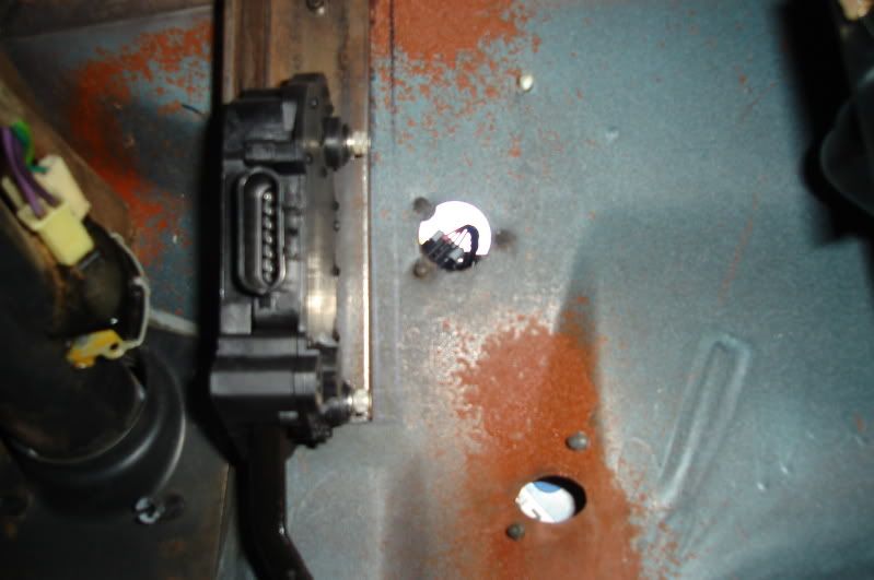 After marking the outline of the 2-1/8" hole using a piece of 2-1/8" O.D. exhaust tubing (2" pipe expanded for a slip fit over 2" pipe) I drilled a series of small holes just inside the line. 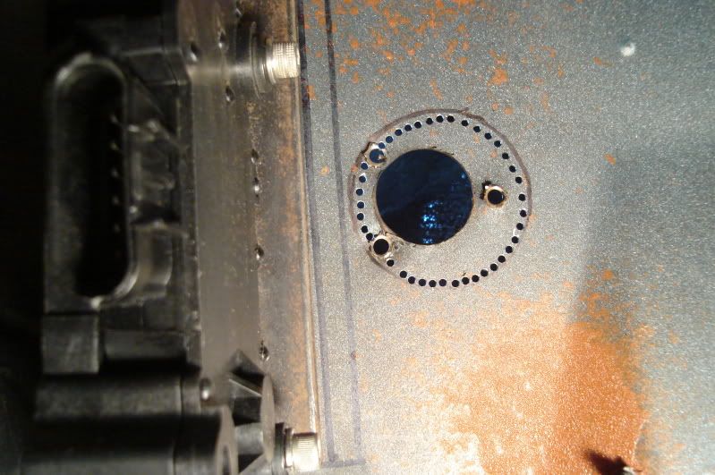 A sharp chisel was used to make quick work of the material that was left between the holes, a half-round file finishes off the edges. 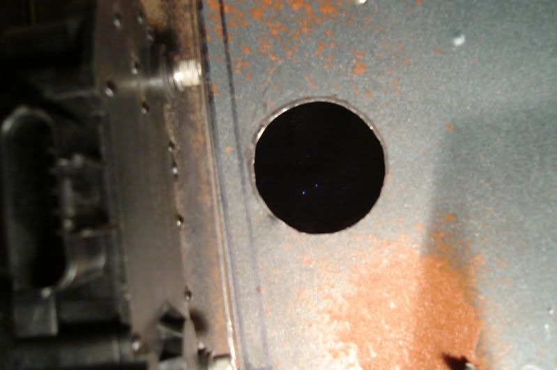 My next dilemma, how to go about getting the harness through this grommet and proerly sealing the grommet to both the firewall and harness. Clearly the harness can't fiit through the grommet without cutting the I.D. of the grommet. The big harness junction shown here would take about a 1" hole stretched out to 1.5" at the very minimum to pass it through the grommet, the grommet only has a 5/8" hole in it. What to do? Cut the hole a little bigger and try work the entire engine side of the harness through the grommet, or slice it down one side and just slip it over the main cable bundle. Even if I slice it the 5/8" hole still won't be big enough for the 15/16" diameter main cable bundle to pass through. Any opinions or personal experiences would be much appreciated. 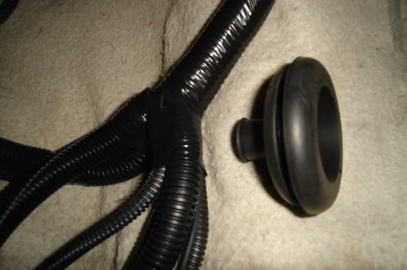 Made a little more progress this weekend, thanks for looking!
|
|
#297
08-10-2009, 01:04 AM
|
||||
|
||||
|
Bart,
Looking gooder. I believe I would slice it, trim the small opening to fit main cable, silicone the slice and inside/outside real good and let it sit to harden then snap it in place. Charles |
|
#298
08-10-2009, 07:24 PM
|
||||
|
||||
|
I have sliced many grommets in my time. If done properly, you really don't need to silicone. If you do silicone it, I would do it after the grommet is installed in the firewall. Actually, I'd wait until the car is running & done.
Just my .02
__________________
Tod Hoffmann 1966 GTO Montero Red Hardtop - Holley EFI'd 462, KRE DPorts/Muncie 4spd 1990 Chevy 454SS pickup - Accel DFI/T56 6spd - Hot Rod Power Tour Long Hauler 1996 Chevy K2500 ECSB 'Poopy' 2002 Honda VTX1800C 2016 Cadillac CTS Premium My project thread: http://forums.maxperformanceinc.com/...d.php?t=516826 
|
|
#299
08-10-2009, 11:21 PM
|
||||
|
||||
|
Thanks for the suggestions guys.
I think I'll get a new razor blade and slice it so I can spread it and close it over the harness after I feed it all through the hole in the firewall. I agree that it should close up pretty tight after I shove it through the hole in the sheetmetal. If I need to seal it up around the harness and at the the cut line a little better I'll use some non-hardening black 3M strip caulk to take care of that. |
|
#300
08-15-2009, 01:19 AM
|
||||
|
||||
|
Fed the engine harness.....
.....through the hole in the firewall today. I carefully deburred and sanded the inside of the hole smooth with 180 grit paper and touched it up with some black paint to keep the edges from rusting beforehand.
Here you can see where the main harness branches off into several smaller ones, that part of the harness will reside just behind the passenger side cylinder head. 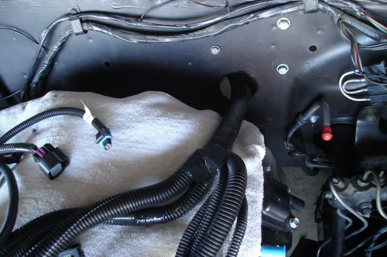 I cut the hole in the grommet to 3/4" using a piece of 3/4" I.D. tubing with the end sharpened, the main harness is about 15/16" in diameter. Using a fresh new razor blade I made a cut in the grommet. 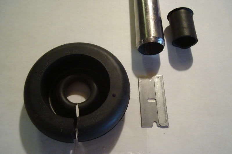 The engine harness fits pretty nicely, there is enough room for it to tuck against the firewall away from the back of the engine. The grommet went in easily and will need some sealer around the harness later when I'm through messing with it, if I don't like the way it's working out I can buy an aftermarket split grommet later on. The wiring provided (blue, green & pink) for control of the fan relays can be seen at the very bottom of the pic. I have two Bosch 30 amp relays here (0 332 019 150) that perhaps I can use for the fans, I'm not sure if they're the correct ones to use. 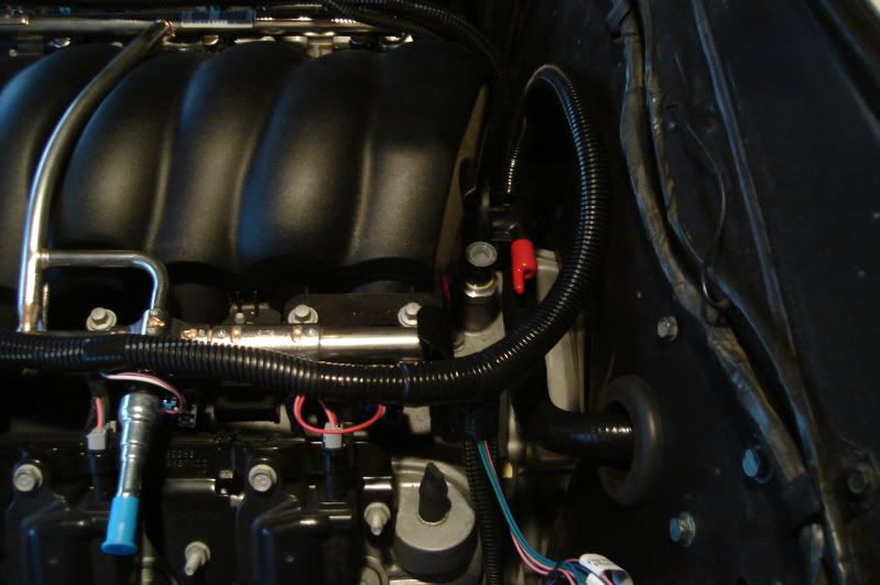 I need to come up with a bracket or plate to mount the ECM (Engine Control Module) in this spot just to the left of the passenger side kick panel. I can't get it mounted up any higher as it will interfere with the A/C unit. It will be up high enough to be out of the way of my passenger's feet, but still easily accessible. 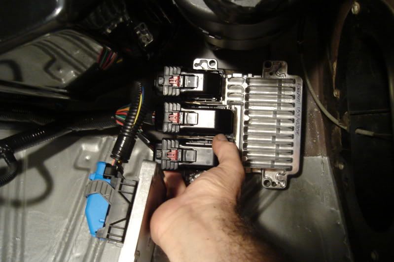 I can mount this TCM (Transmission Control Module) unit over the top of the ECM, leaving about an inch of air space between them for cooling airflow. 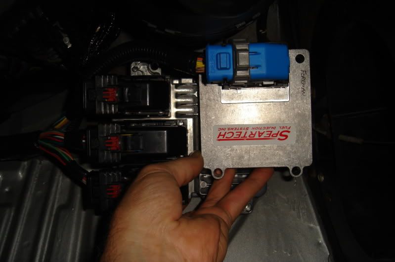 With the engine side of the harness out of the way it doesn't look too bad in here. On the driver's side you can see the 4 fuses (#1- Battery, #2- Injection & Ignition, #3- O2 heaters, #4- Fuel pump) which can be mounted right next to the original fuse panel. On the trans hump is the diagnostic port/check engine light unit. Closer to the firewall on the hump is the wiring rolled up for the cruise control, brake switch (for cruise control disengagement, needs to be a 4 terminal type of brake switch), tach, electric speedo (which I won't be using) and A/C compressor. On the passenger side is the ECM unit and fuel pump relay. The ETC (electronic throttle control) pedal harness has a little extra length that will need to be looped and tied up. All in all it should be a pretty simple and neat installation when it's done, of course figuring a few things out along the way will be more than just a little challenging. 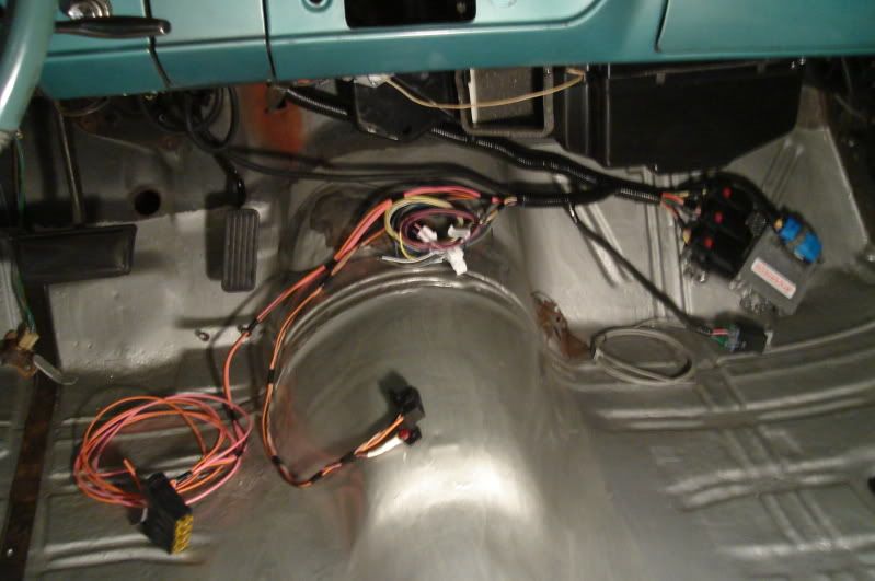 Tomorow I'll try to fab up the mounting brackets I need for the ECM and find a home for the fuses, fuel pump relay and diagnostic port/check engine light unit. |
| Reply |
|
|
The PY Online Forums is the largest online gathering of Pontiac enthusiasts anywhere in the world. Founded in 1991, it was also the first online forum for people to gather and talk about their Pontiacs. Since then, it has become the mecca of Pontiac technical data and knowledge that no other place can surpass.






 Linear Mode

